Guest Post by Dan Lamone
 Designing a production process for UV curable resins requires production engineers to consider several main design variables: spectral output (wavelength), coverage area, energy density and peak irradiance (light intensity). This week’s post will focus on the first two variables while next week’s post will focus on energy density and power density.
For your UV source to interact with the UV resin’s photoinitiator, the spectral output of the UV source must match the photoinitiator’s absorption spectrum. If the UV source is a lamp technology, three common metal halide bulb types are used: H/H+ bulb (mercury), D-bulb (iron iodide) and V-bulb (gallium iodide). The spectral output for each of these three lamp types is shown below in Figure 1.
Figure 1: Metal halide bulb spectral output.
The H+ spectral output is predominately in the UV-C range, 200-300nm) which best applies to thin surface coatings as UV-C radiation is rapidly absorbed by organic materials or those UV curable resins used benzophenone-type or UV-C initiators. The most commonly used UV bulb is the D-bulb, with its main spectral emissions in the high UV-A range (360-400nm). Many UV curable resins now employ initiators that best function in the UV-A range to increase depth of penetration. The predominate spectral emissions for V-bulbs is in the UV-A-visible radiation transition zone (400nm) – these bulbs will produce a violet-colored tone – and are commonly used in white or heavily pigmented systems.
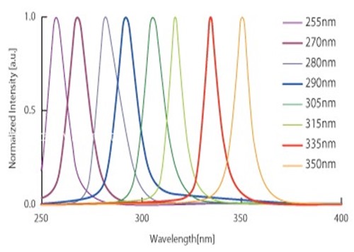
A characteristic of all 3 lamp types, most especially the H/H+ and D bulbs, is that the total spectral emissions cover a wide range of wavelengths. This is in stark contrast to emerging UV LED technologies where wavelength bands for different LED’s are far more narrow. Figure 2 below demonstrates the wavelength range and potential UV spectral outputs for UV LED technologies.
Figure 2. Example UV LED emission spectra. Graphic Courtesy of Nikkiso.
The UV LED spectra shown in Figure 2 are by no means representative of all possible wavelength configurations, several more, especially in the high UV-A region exist. However, the electroluminescence function employed by LED’s will ensure that the spectral range for each diode-type will by far more narrow than the electric arc mechanism used by bulb/lamp technologies. A production engineering must be very attentive to matching the photoinitiator absorption spectrum and LED spectral output.
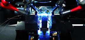
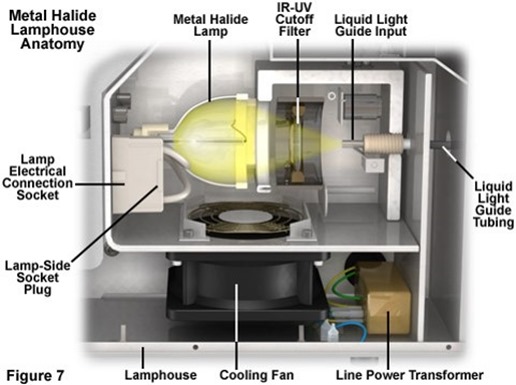
After aligning the bulb spectral range with the photoinitiator’s absorption spectrum, the next design consideration is the coverage region you need for your UV source to cover. Many tacking and glop top applications, whose dispensing area is less than one square inch, employ spot cure UV technologies. Spot cure units focus UV radiation into a light-tube (or light-guide) that allows an operator to precisely guide the UV radiation to the UV curable resin. Many applications will use multiple spot cure light guides in parallel to cure multiple dispensed resins simultaneously. A photo of such an application is shown in the introductory image of this post. Spot Cure technologies can be UV lamp or LED based in design. Figure 3 below shows the engineering design of a UV lamp spot cure unit that uses a metal halide lamp as its source.
Figure 3. Metal Halide Lamphouse Anatomy. Photo Courtesy Carl Zeiss Microscopy Online Campus
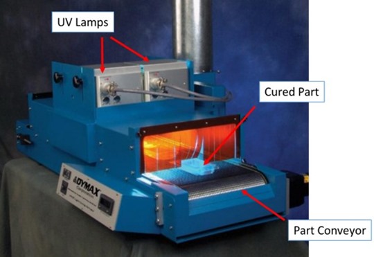
Should your application require UV coverage areas greater than 1in2, most processes will use flood style systems that are designed to spread the UV radiation over larger surface areas. Most single-housing flood lamps expose ~36in2 (6”x6”), while LED systems can be configured in almost any fashion. Larger surface areas for large parts or film based coatings, flood lamps can be configured in parallel to expose across larger widths. Figure 4 below shows a conveyor flood system with two UV lamps in parallel to expose across a 12” width.
Figure 4. Conveyor Flood UV system. Photo courtesy of Dymax


Your information in the Blogs are excellent in explaining what I see as a complex topic and bringing to clean and understandable .
It has helped me significantly in understanding our process in Can production . I would ask one question if it’s possible and that is
We currently cure lacquer on the can chime at a mat speed of 19 m/ min. The Puck reading we take is 200 mj on the A ray . We wish to increase the mat speed to 30 m/min and from my understanding the Dose is inversely affected . Now to maintain the 200 minimum the plan is to give the can another lamp that will be placed in line 0.5 m after the 1st . This is based on the theory that the 2nd lamp continues the cure to achieve the required 200mj . I do not believe this approach is correct so would ask your advice on the theory and how it calculated