 In the previous post we discussed the challenges of capillary underfills. This post will focus on some of the technical aspects required to formulate an effective underfill.
As can be seen in the above figure, traditional capillary underfills are typically provided in syringes (or cartridges) and consist of a formulated mixture of thermoset resins and fillers. The resins and fillers are tailored to achieve the following properties:
- Good flow under the die (chip)
- Wetting of both the die front side passivation and the soldermask on the flip chip BGA (FCBGA)
- Proper void-free filling and fillet formation to enable high package reliability
- Proper physical and mechanical properties such as CTE, glass transition temperature (Tg), modulus, and low moisture absorption
Some of the package technical drivers that influence capillary underfill performance are the bump height, bump density, and die size (flow length). As the bump height decreases and the die sizes increase, the flow challenge increases. Traditional filler sizes are too large for the smaller geometries. In order to keep the rheology tailored, low viscosity resins are used. Liquid epoxies are the most common types of thermoset monomers used. The epoxy chemistry tool box leads to a wide variety of potential options for formulators. For example, bisphenol F epoxy is liquid and can be used as a low viscosity resin carrier.
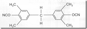
The majority of capillary underfills are epoxy-based, but there are some commercially available underfills based on liquid cyanate esters (bisphenol F dicyanate), and a low moisture absorption liquid dicyanate monomer is tetra methyl bisphenol F dicyanate. The cyanate group (OCN) contains a triple bond and with suitable coordination catalysts forms triazine rings with high Tg’s and low concentration of polar groups (making the resin hydrophobic).
The second key aspect of capillary underfills is the technology associated with the fillers. Important parameters are:
- Filler size
- Packing density
- Thermally conductivity (silicon vs boron nitride)
To address the fine solder bump or copper pillar pitch along with the narrowing gap, the filler size must decrease. In the following figure from Namics (IMAPS 2013), one observes the filler size decreasing to around 0.3 microns over time.
To achieve very low CTE’s, high filler loadings are required. To get high filler loading, generational packing techniques are used. In generational packing, there is a specific relationship between filler particle radii. Using generational packing strategies, the finer filler particles are able to fit into the intertices of the larger particles. The following figure summarizes the generational packing technology:
One observes the second filler size is about 41% of the largest particle radius and the second smallest filler is about 22% of the largest particle radius. As the filler loading increases, the CTE decreases. Formulators work hard to optimize the resin viscosity, filler packing, and resin-particle interface to achieve the best flow and final fully-cured physical properties.
During dispensing, the FCBGA substrate is heated to approximately 90-100°C and the underfill is heated in the transfer lines and nozzle (not the syringe, which would cause poor working time). Heating drops the viscosity and also eliminates most shear thinning resulting in a low viscosity, Newtonian fluid that can easily flow under the flip chip. In the following figure, the dispensing geometry is shown.
The next post will focus on the shift from capillary underfill to pre-applied underfills such as No Flow (NUF).


Leave a Reply