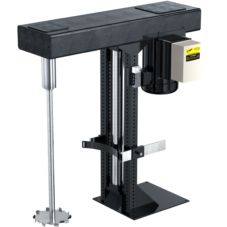
This post will cover the simple case where high shear is required without vacuum degassing. The mixer consists of a single shaft with a Cowles dispersing blade mounted on the end. The image below is from Mixer Direct (Mixer Direct high speed disperser )
In the image above, the mixing vessel is not shown in order to visualize how the dispersing blade would be positioned. Depending on the batch volume, the horsepower and mixing vessel size needs to be determined. A standard rule of thumb is 1 HP for every 10 gallons of product. This estimate works well for mixing materials with viscosities up to approximately 50,000 cps [1]. Once the formulation is close, manufacturing trials are required to “fine-tune” the filler loading and order of addition to obtain optimal rheological properties. Typically, the low viscosity resin(s) are added first and blended together. Having a low resin viscosity will aid in both dispersing and wetting of the fillers.
For many types of highly-filled formulations, high shear dispersion is required to achieve optimum final properties. The tip speed (peripheral velocity) is a critical variable in the dispersing process. The tip speed (in feet/minute or fpm) can be calculated:
fpm = RPM X 0.262 X blade diameter (inches)
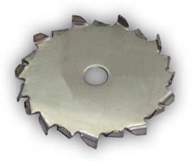
Typical tip speeds are in the range of 1,800 – 6,000 fpm. Careful experiments need to be performed to determine the optimal tip speed to get proper dispersion and rheological properties. For most high speed dispersing applications a Cowles dispersing blade is used and is shown in the following image:
The “saw tooth” type blade provides high shear in the mixing vessel. The Cowles blades rotate in a clockwise manner and have usually have a rotation arrow stamped on the blade to ensure proper orientation of the mixing shaft. Most dispersing blades are easily removed for cleaning and optimizing the size depending on the mixing vessel size and volume.
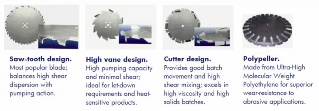
There are other types of dispersing blades available depending on the type of filler, the desired dispersion, the batch viscosity and the abrasive nature of the fillers being dispersed. The following image shows several types of blade designs (courtesy: Charles Ross and Son Company [1]):
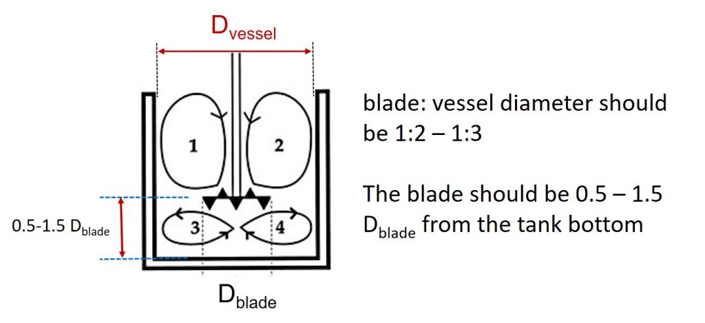
The second critical variable is the geometry in the mixing vessel. As shown in Figure 1, the placement of the dispersing blade relative to the vessel walls and the bottom is key to get good flow and dispersion.
Figure 1. Blade diameter and location for optimal mixing (sources: Degussa [2] and MorehouseCowles [3])
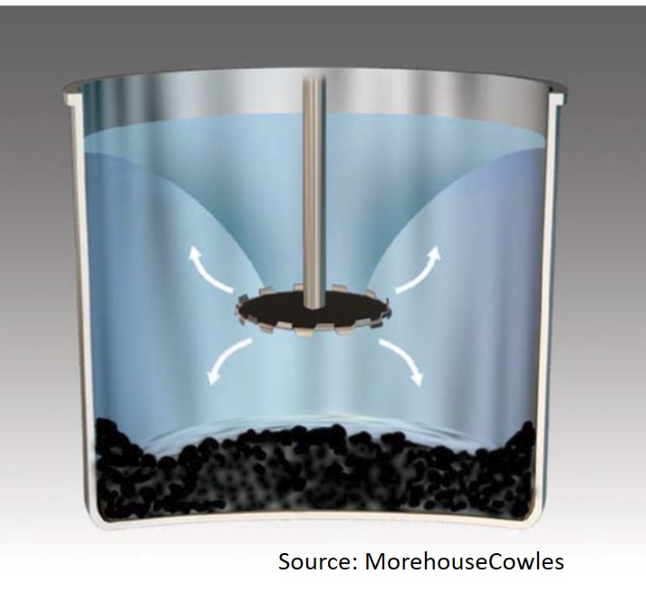
The objective of the dispersing process is to establish a strong vortex that extends down to the blade while ensuring good material movement into the dispersing blades and off the bottom of the tank. If the blade is too small, the material will often cling to the vessel walls and a weak vortex will form resulting in long dispersion times. As shown in Figure 1, four mixing zones should be active. Zones 1 and 2 pull the material off the vessel walls and into the dispersing blade. Zones 3 and 4 pull the material off the bottom of the vessel and into the dispersing blades.
In Figure 1, a range of values is presented. Degussa recommends the blade: vessel diameter to be in the range of 1:2 to 1:3 (ref [2]). MorehouseCowles dispersion instructions suggest the blade:vessel diameter to be 1:3 (ref [3]). More generally, MorehouseCowles recommends the dispersing blade should be 1 to 1.5 diameters off the bottom of the tank.
Degussa recommends a tip speed of at least 1800 fpm and MorehouseCowles suggests tip speeds in the range of 4,000 – 6,000 fpm. The lesson here is that for each formulation, careful experiments should be performed to evaluate all of the appropriate process parameters, such as tip speed and the dispersing blade geometry and placement.
Guidelines for dispersing:
- Blade speed too slow: long dispersion times and potential for material settling as shown in the figure below. Tip speeds in the range of 4,000 – 6,000 fpm (as calculated using the equation above) typically yield good dispersions.
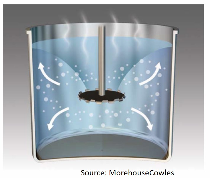
- Blade speed too fast: results in pulling air into the product, excess heat build-up and low quality dispersion
- Blade too small: material near the vessel wall will not be pulled into the dispersing blade resulting in poor overall product movement and potential for filler settling
- Blade too large: result in pulling air into the product and not achieve optimal product movement into the dispersing blades.
- Blade too low in mixing vessel: decrease product movement at the top of the tank and potentially create dead spots that will not be dispersed properly.
- Blade too high in mixing vessel: flow off the bottom of the tank will be decreased potentially allowing filler settling in the bottom region and not get dispersed, poor overall material movement and potential for air entrapment
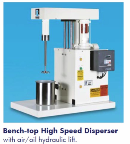
The discussion above relates both to volume manufacturing and lab-scale development work. Most of the major mixing equipment manufacturers provide dispersion equipment at the lab-scale as shown in the image below (courtesy: Charles Ross and Son Company [1]):
If possible, a lab-scale mixer should be used during formulation development allowing experiments to be performed to determine the order of addition, tip speed, and quality of dispersion. Rheological methods are very useful during formulation development and mixing experiments to characterize the viscosity shear-rate relationships which can be used to determine dispersion quality.
References:
- Ross White Paper “All About High Speed Dispersers”
- Degussa, Successful Use of Fumed Silica in Liquid Systems
- MorehouseCowles presentation “Fundamentals of Dispersion”

Leave a Reply