This post will discuss the rationale for using thermal interface materials. The question is: why would someone go to through the effort to put a thermal interface material (TIM) between two surfaces? To answer the question, let’s take a closer look at the interface between two surfaces. Figure 1 shows a schematic of two typical surfaces when placed in close contact.
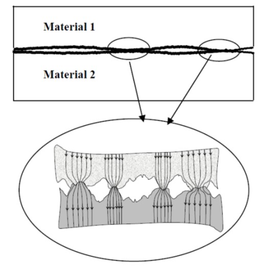
Figure 1. Schematic of two materials in contact (from [1]).
In reality, no surface is perfectly smooth and actual surfaces typically have surface roughness as shown in Figure 1. When the two surfaces are placed in contact, the contact area is defined where the high points on each surface touch as seen in the lower part in Figure 1. The point-to-point contacts are where the heat transfer occurs across the interface. The heat flow paths are shown schematically in the lower part of Figure 1. Good heat transfer requires intimate contact between the two surfaces. Note that between the point-to-point contacts are air gaps. Air is a poor thermal conductor, so the higher the surface roughness, the lower the overall heat transfer will be.
Thermal interface materials are utilized to eliminate or minimize the air gaps between the two surfaces. In Figure 2, an idealized cross-section is shown depicting the placement of a TIM between two objects. Note there are three regions in the TIM that is in the gap between the two objects; the first is the bulk of the TIM (grey area) and the second is the interfacial layers on both sides of the TIM. The combination of the interfacial resistance and the TIM thermal resistance is termed the “thermal contact resistance” in Figure 2.
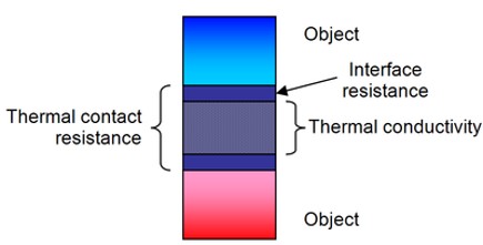
Figure 2. Idealized thermal path between two surfaces (objects)
As discussed above, actual surfaces are not flat and have some degree of surface roughness [1]. The effective total thermal resistance between the two objects consists of:
- The interface resistance between surface 1 and the thermal interface material
- The bulk thermal resistance of the TIM
- The interface resistance between surface 2 and the thermal interface material
Figure 3 shows a schematic of a thermal interface material inserted between the two objects.
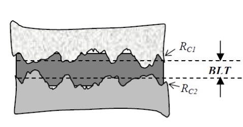
Figure 3. Thermal interface material inserted between two bodies (from [1])
In Figure 3, BLT is the bond line thickness and Rc1 and Rc2 are the contact resistances of the TIM at the two surfaces.
The effective total thermal resistance is expressed as [2]:
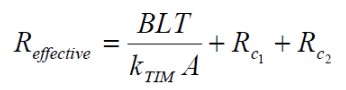
Where:
Reffective is the total thermal resistance
kTIM is the thermal conductivity of the thermal interface material
A is the cross-sectional area
BLT is the bond line thickness
Rc1 and Rc2 are the contact resistances of the TIM at the two surfaces
In order to increase the heat flow across the interface, it is critical to minimize Reffective. In the equation above, note that the interfacial contact resistances are additive and thus it is very important to understand what controls the contact resistance. The goal is to decrease the contact resistances. Additionally, the bond line thickness (BLT) is proportional to Reffective so decreasing the bondline thickness will increase the heat transfer (or decrease the thermal resistance). The thermal conductivity of the TIM should be as large as possible to decrease Reffective.
The contact resistance is controlled by a number of factors such as surface roughness, clamping pressure, the TIM compressive modulus, surface energy (for wetting) and the TIM rheological properties [1]. One can see that flow, wetting, and surface chemistry may play important roles in decreasing the contact resistance.
References:
- Sarvar, F., Whalley, D.C. and Conway, P.P., 2006. “Thermal interface materials – a review of the state of the art.” Proceeding of the 1st IEEE Electronics System Integration Technology Conference, Dresden, September 2006, vol. 2, pp. 1292-1302.
- Blazej, D. “Thermal Interface Materials,” Electronics Cooling,” Vol 9, no. 4, pp. 14-20, November 2003.
Leave a Reply