 In the previous posts in this series we have presented the fundamentals of dielectric cure monitoring and have shown how the dielectric loss factor can be a way to monitor the viscosity changes that occur during thermoset curing. The previous posts also showed how the frequency response can be observed to determine either the glass transition temperature on heating or vitrification during curing. In this post we will ‘put-it-all-together” to show how dielectric cure monitoring can be used to monitor the viscosity changes during a composite lamination process.
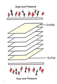
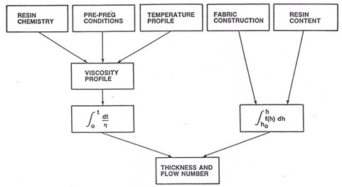
During the lamination process, the B-staged prepregs are subjected to a non-isothermal heating rate up to the final cure temperature. The viscosity profile is an important process variable:
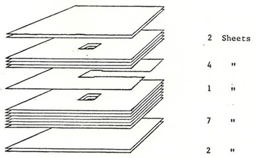
To characterize and optimize the lamination process, it would be good to have an in-situ method to measure the viscosity profile for various process variables (heating rate, final cure temperature, number of prepreg plies, etc.). The microdielectric method described earlier in this series provides a nice way to measure the cure profile. The microdielectric sensors were mounted in the prepreg layup as shown in the following figure. The thin lead was allowed to exit the layup and to accommodate the sensor thickness and prevent crushing, small openings were provided for the top and bottom of the sensors. Additionally, a small amount of prepreg powder (shaken off the glass cloth from the same lot of prepreg used in the layup) was placed over the interdigitated comb electrodes. The prepreg powder would soften and provide good coverage between the comb electrodes allowing a good dielectric signal.
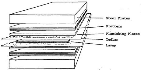
In the following figure, the lamination layup stack is shown.
Heavy steel caul plates are used on the top and bottom of the stack. The heating rate is controlled by the number of “blotter” layers. The blotter paper is a heavy paper stock and the more layers of blotter paper, the slower the heating rate. By changing the number of blotters, the heating rate can be controlled. Next a set of polished planishing plates are used to provide a smooth surface for the prepreg stack-up. A sheet of Tedlar (fluoropolymer release film) is placed on the top and bottom of the prepreg stack-up to prevent the prepreg from adhering to the planishing plates after the stack is cured. In the center of the layup is the prepreg stack with the embedded microdielectric sensor.
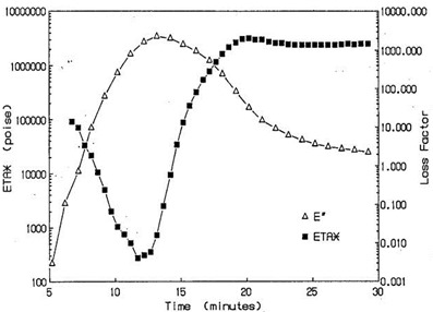
In this case, a prepreg with a fully cured Tg = 170oC was used and the press temperature was set to 175oC. During non-isothermal curing, the dielectric loss factor and complex viscosity were measured simultaneously:
One observes that the viscosity profile is related to the dielectric loss factor in an inverse manner. The loss factor goes through a maximum in the vicinity of the viscosity minimum. In the lamination studies, the dielectric loss factor was monitored during several press runs. For each press run, the number of blotters was changed (from 3 to 7, thus resulting in a faster heating rate for 3 blotters, to a slower heating rate as the number of blotters increased).
In the following figure, the dielectric loss factor is plotted as a function of time for the various heating rates (i.e. # of blotters):
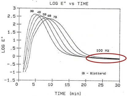 At the fastest heating rate, we observe the highest value of the E” (or the lowest viscosity minimum). This is expected from the results previously show in earlier posts. As the heating rate slows, the minimum viscosity increases and the data clearly shows the dielectric loss factor maximum systematically decreases as the heating rate slows. Also, there is no evidence of dipolar relaxations at long times. This is to be expected since the fully cured Tg is lower than the final cure temperature thus vitrification cannot occur during curing.
In the above curves, the dielectric loss factor signals all approach the same value after about 25 minutes (see the red oval). When the dielectric loss factor reaches the same value, this indicates that the thermoset resin is achieving the same fully cured network structure. When the fully cured network (and final Tg) is achieved independent of the cure path (in this case the various heating rates to the cure temperature), the curing system is said to be cure path independent. This is a good thing. Cure path independence allows the process engineer to tailor the flow (width and depth of the viscosity window) to achieve good wetting, ply consolidation, and flow over circuit features having confidence in that as long at the final press temperature is above the fully cured Tg, the final network properties will be the same.

Leave a Reply