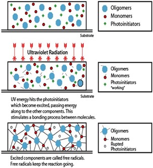
 I’d like to thank Dan for his series on UV curing of polymers. As was pointed out, UV curing has many advantages over thermal curing in some applications. Since I am a structure-property-process-property type of guy, the question is; how do you characterize UV curing of thermosets. In the next couple posts we will discuss UV rheology methods and provide some key characterization examples. Subsequent posts will cover UV Differential Scanning Calorimetry (UV DSC) and how the photo curing kinetics can be measured.
Let’s now turn our attention to a method to characterize the impact of UV exposure on the rheological properties of thermosets during curing. From a practical point of view, there are several commercially available accessories that can be used on various brands of rheometers. TA Instruments has a UV rheology kit (1), ATS RheoSystems/REOLOGICA Instruments (2) has a UV rheometer, Malvern Instruments has published information on a UV rheometer using a Kinexus rotational rheometer (3), and there have been published articles by researchers that developed in-house modifications to rheometers to follow the UV curing of thermosets (4, 5). I have used the UV rheometer accessory from TA Instruments, so I will use that experience and some data from a nice TA Instruments applications note (1).
There are several technical challenges that have to be addressed in order to accurately measure the rheological changes during UV irradiation. The first is that the UV curing kinetics are very fast requiring modification of the data acquisition equipment. In a typical UV curing reaction, the materials react in seconds and the viscosity and moduli can increase 2-5 decades in this short time period. Additionally, as Dan pointed out in previous posts, careful measurement of the UV intensity at the sample is critical to get a precise UV dose. Also, the UV light needs to be uniform across the sample and sample thickness is important due the the penetration depth of various types of UV energy.
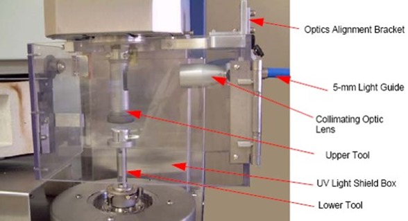
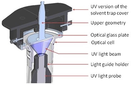
The images below show type examples of how a parallel plate geometry can be modified to allow for the UV light path into the sample. It should be noted that oscillatory parallel plate fixtures are the preferred geometry. Additionally, it is easy to use UV transparent (quartz) parallel plates to facilitate uniform light transmission into the sample. The gap can also be carefully controlled in the parallel plate geometry.
 Image Courtesy of TA Instruments
 Image Courtesy of Malvern Instruments
In either case several common elements can be noted. TA Instruments uses a UV light shield enclosure to limit the amount of ambient UV light hitting the samples. The Malvern Instruments encloses the UV light guide in the lower tool and provides a cover over the parallel plates. In either case, a UV light guide is employed to direct the UV beam towards the parallel plates. In both cases, the parallel plates are made of a UV transparent material.
In the next post we will present data on the the rheological changes during UV exposure.
References
1) TA Instruments, Applications Note AAN021
2) RADTECH REPORT, September/October 2004
3) Using the Kinexus Rotational Rheometer for In-Situ Characterization for the Rheological Properties of UV Curable Materials.
4) Sang Sun Lee, Andre Luciani, Jan-Anders Manson, Progress in Organic Coatings, V. 38, Issue 3-4, June 2000, P. 193
5) Yasufumi Otsubo, Takashi Amari, Koichiro Wantanabe, J. of Applied Polymer Science, Volume 29, Issue 12, December 1984, Pages 4071–4080

Leave a Reply