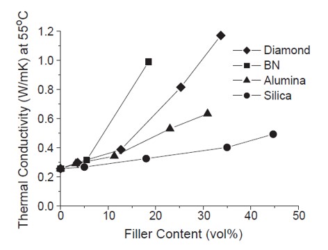
 The last post showed how fillers play an important role in the development of thermal conductivity. The filler volume percent is a key parameter as shown in the figure on the left. To complete the discussion, two other characteristics need to be presented. The first is the concept of the percolation threshold and the second in the particle morphology. We touched on morphology a little bit in the last post.
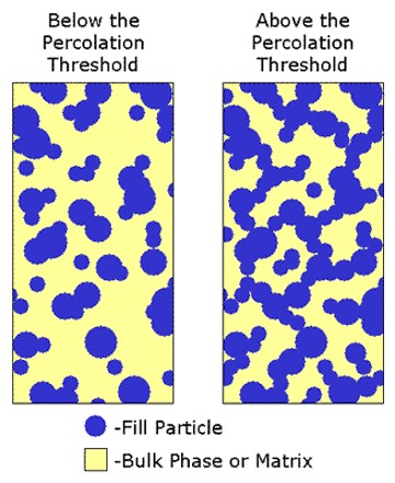
With respect to achieving high thermal conductivity, good particle-particle contact is required since thermal transfer is governed by phonon-phonon coupling [reference]. In order to develop thermal conductivity, the filler particles must form a conductive path from one side of the thermal interface material to the other, that is between the two surfaces in contact with the TIM. If the filler loading is too low to develop a connected path through the resin matrix, the TIM will not be thermally conductive. A schematic of the filler loading in a TIM is shown in Figure 1.
Figure 1. Schematic of filler loading at two levels showing the percolation threshold on the right side.
In Figure 1, the polymer matrix (insulating resin) is shown in yellow and the filler particles are blue. On the left side in Figure 1, the particle-particle interactions do not form a continuous path through the adhesive. This represents a condition below the percolation threshold. At the percolation threshold, a continuous path develops, and thermal conductivity rapidly increases. Achieving filler loading above the percolation threshold meets the first requirement. Careful experiments are conducted at increasing filler loadings until there is a dramatic increase in the thermal conductivity.
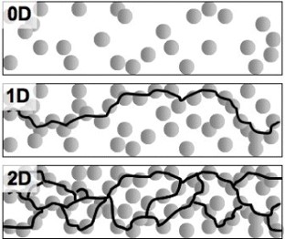
The second requirement is to achieve good particle-particle contact. The filler morphology and size are important variables. In order to achieve the percolation threshold, a single path is necessary, but having a 2D or 3D network facilitates thermal conductivity development. In Figure 2, a schematic shows 0D, 1D and 2D filler particle connectivity.
Figure 2. Schematic of multi-dimensional filler packing
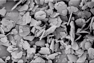
In Figure 2, the thermal conductivity will be significantly enhanced due to the filler loading and connectivity associated with the percolation threshold via 1D type connectivity. With the development of 2D connectivity, the thermal conductivity will be further enhanced. Figure 2 shows the development of the thermal path using a spherical particle. As observed in the top figure, boron nitride (BN) is very efficient at increasing the thermal conductivity of an epoxy composite. Figure 3 shows a scanning electron micrograph (SEM) of BN filler particles.
Figure 3. Scanning electron micrograph of boron nitride filler
Note the plate-like morphology of BN. The flat plate type filler allows for larger particle-particle packing. Think about the contact area between stacked poker chips versus glass marbles. The BN filler aspect ratio and the plate-like morphology allow for the development of a three-dimensional filler-filler network and an increase in the thermal conductivity of the composite.
An additional benefit is that the increasing filler loading decreases the coefficient of thermal expansion (CTE) as shown in Figure 4.
Figure 4. Coefficient of thermal expansion (CTE) versus volume percent filler loading for various types of fillers [1].
In the same way that BN was effective at increasing the thermal conductivity of the epoxy composite, BN is also very effective a reducing the CTE of the same epoxy composite as shown by the curve on the left in Figure 4. The BN particle morphology and loading level plays an important role in the control of both the CTE and the thermal conductivity.
References
- Sun Lee and J. Yu, Diamond and Related Materials 14, 1647 (2005).


Leave a Reply