This post will cover the types of rheological measurements available for characterizing thermosets. Rheology is important in two aspects of thermoset processing. The first is during the application or dispensing of the uncured thermoset (for example an highly filled adhesive or coating) and the second is characterizing the viscosity changes during the curing process. In the first case, the viscosity may change dramatically as a function of the shear rate (or stress) for highly shear-thinning materials even with no chemical curing taking place. On the other hand, the viscosity may change by several orders of magnitude simply due the curing reaction (chain extension in the early stages of cure followed by crosslinking later in the curing process).
Let’s start with a few basics on the types of rheometers. The viscosity is the ratio of the force (stress) to the deformation rate (or shear rate) as show in the following equation:
To measure the viscosity rheometers measure the stress at a known shear-rate or measure the shear rate at a know stress. There are two types of torsional rheometers:
- Controlled strain (most common)
- Controlled stress
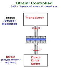
In the case of the strain controlled rotational rheometer, a typical configuration is shown in the following figure:
In this mode, the sample under test is placed between parallel plates (blue in the figure above, but other geometries such as cone-and-plate can also be used) The strain (or deformation) is applied with the direct drive motor and the sample response determines how much torque (stress) is transmitted to the transducer. The strain can be applied using a sinusoidal oscillatory deformation or at a steady shear-rate. It is common to vary the frequency or the shear-rate and measure the viscosity as a function of frequency or shear-rate. Note in this geometry the motor and the transducer are separated.
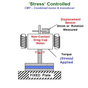
A second geometry is the controlled stress rotational rheometer. The typical configuration is shown in the figure below:
 In this geometry, the sample is again placed between the parallel plates (in blue above) but a torque (stress) is applied using a non-contact drag cup motor (to reduce friction losses). Note that both the motor and strain transducer are in the top housing. When the stress is applied, the material responds by deforming (strain) and the displacement is carefully measured using a precise displacement sensor. This is actually a creep measurement since it is analogous to hanging a weight (apply torque or stress) and then measuring the deformation. A good way to visualize this is to clamp one end of a polymer strip to a fixture, then hang a weight on the other end and measure the deformation (strain) as a function of time. The controlled stress rheometer does the same creep experiment, but in the rotational mode. To measure the viscosity as a function of stress, a series of creep experiments are conducted by applying an increasing stress and waiting for steady state (in order to calculate the viscosity for the steady state shear-rate). We will cover the controlled stress experiment in greater detail in a subsequent post.
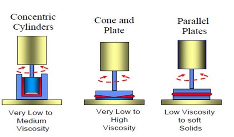
Various sample geometries are available from the rheometer manufacturers.
 For thermosets and especially during curing experiments the parallel plate geometry works best. In addition, most of the rheometers can be equipped with disposable plates for use in thermoset curing studies. Many thermosets are very good adhesives and it would be a bummer to glue your parallel plate fixtures together each time you want to conduct a curing experiment. This could damage your instrument and make it difficult to clean the cured thermosets from the parallel plates without damaging the fixtures.


Typo error;
A second geometry is the controlled strain rotational rheometer.
it should be;
A second geometry is the stress contolled rotational rheometer.
Thanks for the catch! I fixed the typo. Glad to see my readers are sharp!
Jeff
can I know, which rheometer is the best to operate using toothpastes?