 In this post we will introduce the concepts and methods to measure flow using the IPC flow test. Complete details of the test method may be found in IPC-TM-650 (The Institute for Interconnecting and Packaging Electronic Circuits). The flow test measures the percent resin that flows out of a standardized stack of B-staged prepreg for a given lamination process. The test is predicated on only resin flowing during the lamination process. For woven glass cloth prepregs this is a good assumption. There will be a small amount of woven glass deformation and some stray glass fibers along the edges of the test speciment, but as we will see, the flow test compensates for this my measuring the flow in a coupon cut from the center of the test specimen.
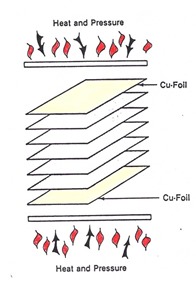
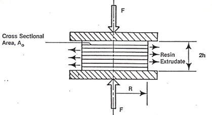
The flow test schematic is shown in the following figure: The flow test details:
- Test specimen is 4 in X 4 in
- Typical flow test uses 4 plies of prepreg (can vary from 4-8 plies depending on the specific lamination process used)
- Laminaton (caul) plates on the top and bottom are typically 0.125 in thick and 6 in X 6 in and made of type 304 stainless steel.
- Lamination press capable of controlling the temperature at 171 ± 3°C at a pressure of 200 ± 10 psi
- Typically have two punches, one for cutting multiple plies of prepreg in 4 x 4 inch squares and a circle punch capable of cutting a circle with 3.192 inch diameter in the sample after lamination (yields a sample after the test that is one-half the original area, πr2 = 8.0 in2 ).
The test procedure:
- Cutting 4 plies of prepreg into 4 x 4 inch samples
- weighing the prepreg stack and recording the weight
- placing the 4 ply stack between Tedlar (type MR) release sheets that are typically the size of the lamination (caul) plates
- Inserting the stack-up into a heated lamination press at 171 ± 3°C
- Apply pressure of 200 ± 10 psi (full pressure should be achieved within 5 seconds)
- Holding the laminate at pressure for a minimum of 10 minutes (maximum time is 16 minutes).
- Releasing pressure, carefully removing the heated stack, and allow to cool to room temperature.
- Using the 3.192 inch diameter punch, cut the circular disk from the center of the laminated 4 x 4 inch sample
- Record the weight of the disk.
The resin flow percent (or flow number) is calculated using the following equation:
Wo = original initial weight of the 4 x 4 inch stack of prepregs (4-8 plies)
Wd = weight of the disc cut from the center of the specimen after pressing
For process control and quality monitoring, prepreg samples are obtained from the moving web, cut into the 4 x 4 inch samples and the resin flow is measured. This gives a discrete value for a given prepreg type (resin content, glass cloth style) that provides an indication of the degree of the resin advancement. The higher the flow number, the lower degree of advancement. A resin with a lower b-stage advancement will have more time to flow (during a given lamination process) and thus will have a higher flow number (resin flow).
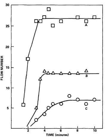
One of the ways to use the flow test to study the lamination process is to conduct aborted flow testing. The standard flow test is run for a given time (not the usual fixed 10 mintes), and at specific time intervals abort the lamination, quickly open the press, remove the layup, cool the specimen, and measure the resin flow. And example is shown in the following figure:
In the above figure the percent flow (or flow number) is plotted as a function of lamination time for three heating rates (Gotro et.al. in Polymer Composites, Vol. 7, No. 2, p. 91, 1986).
In this experiment, the heating rate was controlled by the amount of thermal insulating materials added on each side of the caul plates. Adding more thermal insulating layers decreased the heating rate. As we have seen in earlier posts in this rheology series, the faster heating rates lead to lower minimum viscosities during non-isothermal heating and thus to larger resin flow. The drawback of the aborted flow method is that it is time consuming requiring multiple lamination runs (each data point in the above figure is a discrete lamination run).
In the next post we will introduce the fundamentals of the squeezing flow test and in subsequent posts will show how the squeezing flow test was used to measure the flow versus time in a continuous manner (i.e. one flow test).


Leave a Reply