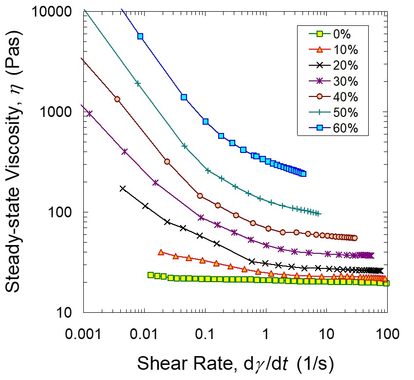
The last post described how to measure the viscosity-shear rate relationship using either a cone-and-plate or a parallel plate rheometer using a shear rate sweep. An example is shown above. This post covers how the viscosity profile influences the dispensing process and provides a short introduction to viscosity modifiers used to control the shear thinning and yield point.
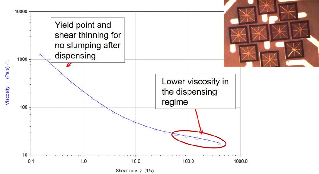
Figure 1. Viscosity as a function of shear rate for a highly filled uncured epoxy formulation.
The viscosity curve in Figure 1 is typical of a highly filled but uncured epoxy formulation used for a variety of adhesive applications. For example, the photograph in the upper right part in Figure 1 shows multiple plastic ball grid array (PBGA) substrates that have a die attach adhesive dispenses on the surface. The dispensing performance is governed by the careful selection of fillers and rheology modifiers (sometimes referred to as thixotropes). At the low shear rates in Figure 1, the viscosity is high and will no slump or sag after dispensing. Die attach adhesives, coil bond adhesives (used in the actuator arm in a hard disk drive), and glob top encapsulants are all formulated to have a specific yield point. The yield point is exceeded during the dispensing allowing for good flow from the syringe through the small dispensing needle onto the substrate.
After the dispensing, you want the adhesive to stay in place and not slump or sag. In the image in Figure 1, the die attach adhesive was dispensed into what is termed a “snowflake” or “asterisk” pattern. The viscosity profile in Figure 1 provides insights into how the rheology is a major factor in the design of an adhesive. As noted before, typical highly filled adhesives have a yield point and during dispensing, the air pressure is adjusted during time-pressure dispensing to overcome the yield point and force the adhesive through the needle.
In the needle, the shear fields break up the structure resulting in a lower viscosity. This is shown by the shear thinning (viscosity decrease with increasing shear rate) in Figure 1. The shear rates at typical dispensing conditions are in the range of 80-500 sec-1 (indicated in the red oval on the right of the viscosity shear-rate curve). The shear stress and shear-rate for a dispensing system is controlled by the pressure, the needle size and needle length.
An interesting note is that in the case of die attach dispensing, the “snowflake” or “asterisk” pattern is used to ensure that after die placement, the adhesive flows uniformly to the edge of the die and forms a uniform fillet. If a single drop of adhesive was placed in the center of the die pad, the flow distance is longer to the four corners than the edges and the non-uniform flow would result in a poor fillet around the edge of the die. The “snowflake” or “asterisk” pattern also prevents air entrapment as the adhesive flows over the die pad on the top surface of the substrate.
We will finish this post with a short description of how fumed silica acts as a rheology modifier.
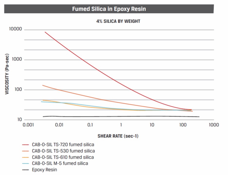
Figure 2. Viscosity as a function of shear rate for an epoxy resin with 4% fumed silica (courtesy of Cabot [1])
Figure 2 shows the relative effectiveness of various types of CAB-O-SIL® fumed silica. TS-720 (top red curve in Figure 2) is a medium surface area fumed silica which has been treated with polydimethylsiloxane and results in a hydrophobic silica with a very different performance compared with untreated silica [1, 2].
In Figure 2, the lowest curve is for the epoxy resin only. Untreated fumed silica is the M-5 curve and exhibits only a small amount of viscosity modification. TS-530 and TS-610 have a different surface treatment. These treated fumed silicas only have a mild effect on the shear thinning behavior. The largest amount of shear thinning is when the TS-720 fumed silica is used as the viscosity modifier. The surface treatment on the fused silica influences or controls the particle-particle interactions and as discussed extensively, the particle responses to the shear fields is a large contributor to the viscosity shear rate profile.
Reference


Leave a Reply