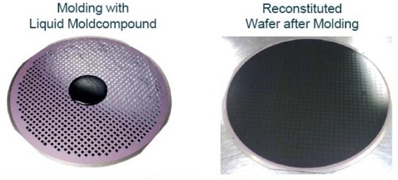
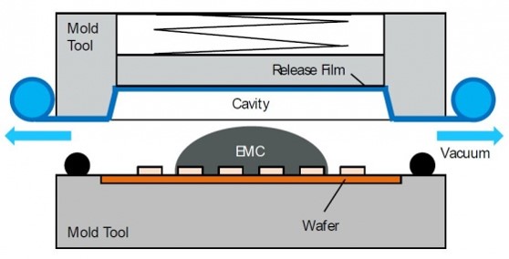
 This post will focus on the epoxy molding process using liquid and solid EMC for FOWLP. In the image on the left, a liquid EMC is shown on the surface of the partially reconstituted wafer prior to compression molding (source: Nanium). For FOWLP, the compression molding process is different compared with the transfer molding process typically used for EMC’s. A schematic of the mold is shown in Figure 1.
Figure 1. Cross-section schematic of compression mold used in the FOWLP process.
For FOWLP, the circular carrier with the known good dies attached are placed in the compression mold. The epoxy mold compound is placed in the center of the mold cavity. In either case, for liquid or solid (granules or powders), the EMC is placed in the center of the carrier. In order to provide release after molding, a release film is placed over the top of the carrier to be molded. In contrast to transfer molding where a release agent (wax additive) is added to the formulation, the release liner is in roll format to easily be changed after the compression molding process.
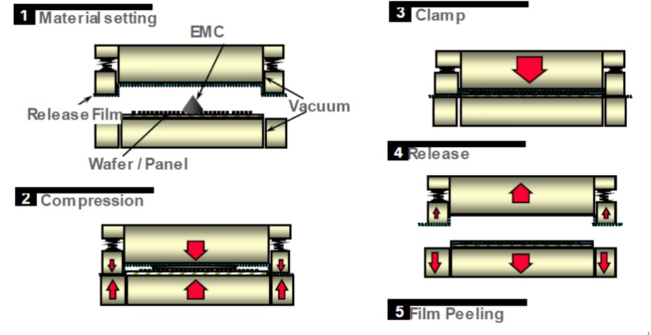
The compression molding process is shown in Figure 2.
Figure 2. Compression molding process for FOWLP (source Nagase Chemtex).
After the carrier wafer and the EMC is loaded into the compression mold (step 1), the heated mold is closed compressing either the liquid or the solid materials (step 2). Upon heating, the liquid EMC will easily flow in the radial direction and encapsulate the dies. A useful aspect of this type of molding is that the circular area allows for uniform flow across the wafer. For a powder or granules, the heating from the platens will cause the material to go through the glass transition temperature (Tg), soften and flow. Once the material has flowed, a clamp pressure is applied to allow for the material to cure. Once the required process time is reached (i.e. the epoxy conversion has achieved a minimum value) the mold pressure is released (step 4) and the mold is opened. Once the mold opens, the release film is peeled off of the now completely encapsulated reconstituted wafer.
Let’s turn to some of our basic thermoset resin processing considerations. In the case of the solid EMC, the first part of step 2 above is to apply heat to soften (liquefy) the EMC. Typical molding temperatures range from 120-150°C. Note that the compression molding temperatures are lower compared with the standard EMC molding process at 175°C. One potential advantage of the lower molding temperature is lower warpage after molding.
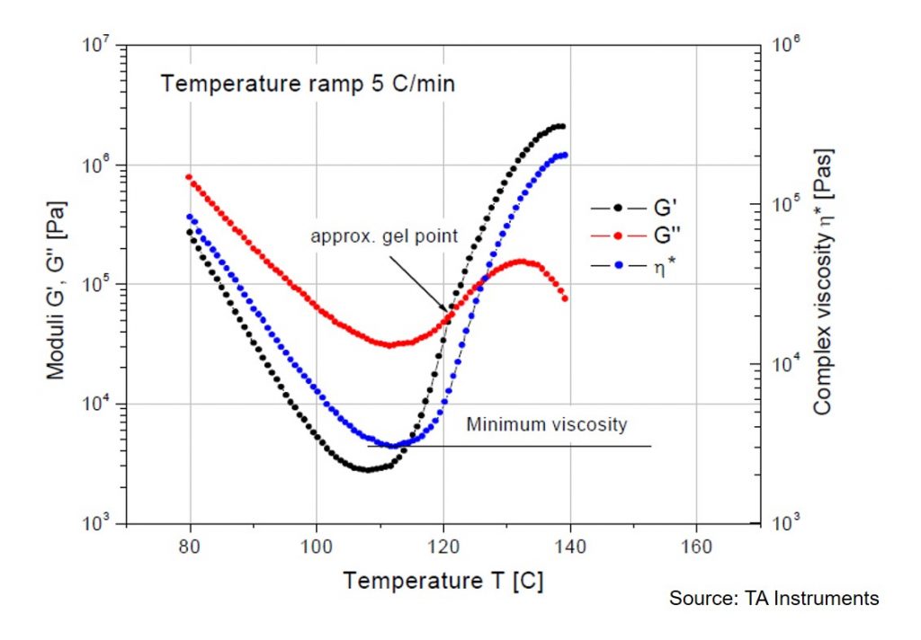
After the Tg is exceeded, the resin viscosity drops dramatically allowing fast flow over the dies and complete encapsulation of all of the dies on the carrier. Now we have to consider the chemorheology of the EMC. Once the material softens at the mold temperature, the lower viscosity allows for good flow and the high mold temperature starts the epoxy curing reaction. In Figure 3, the complex viscosity and the dynamic loss and storage moduli (G” and G’) are shown as a function of temperature.
Figure 3. Complex viscosity (blue) and the dynamic loss and storage moduli (G” and G’) are shown as a function of temperature.
The data above is for illustrative purposes, since the heating rate is 5°C/minute. The actual heating rate in the mold is likely to be much faster, with the result of a narrower process window. The flow window is governed by the Tg on the low temperature side and the temperature of the gel point. At gelation, the macroscopic flow ceases due to the formation of an infinite network. For many epoxy resins, the gel point can be approximated as the cross-over point of G’ and G”. In Figure 3, the approximate gel point occurs at about 120°C. Remember that at the gel point, the material is not fully cured as can be seen by the subsequent increase in the viscosity past the gel point. In the EMC molding process, the epoxy must be cured to past the gel point prior to release from the mold. The conversion at the gel point is dependent on the epoxy chemistry and the hardeners/curing agents used in the formulation (1-3). The conversion at the gel point is always the same, i.e. an isoconversional point since it is controlled by the stoichiometry and not the process. The conversion at the gel point for epoxy/amines systems ranges from 30-60% depending on the stoichiometry.
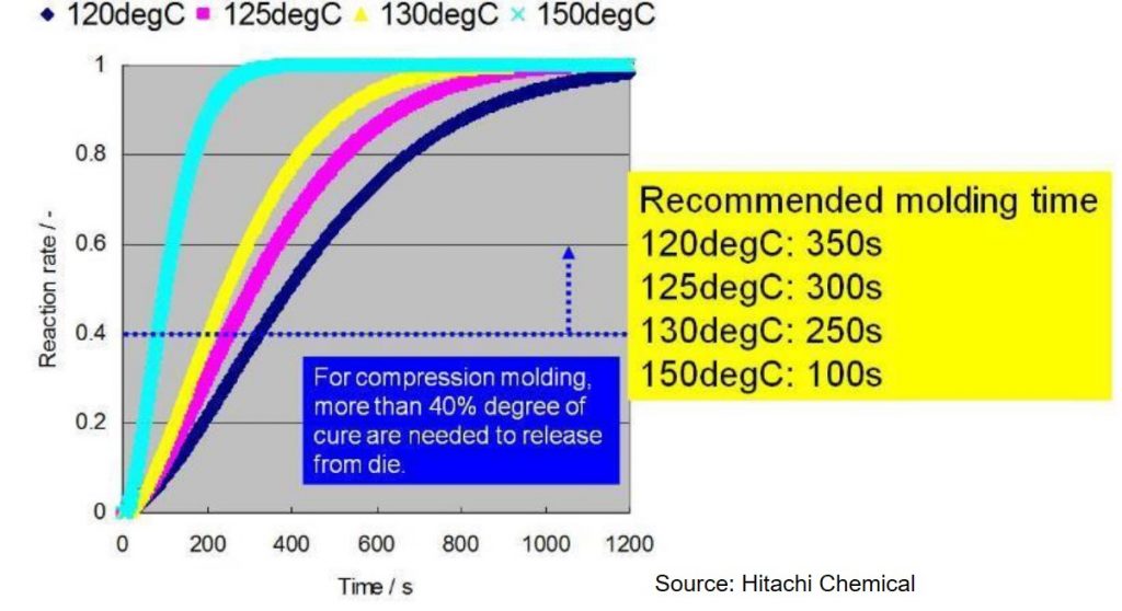
Figure 4. Degree of cure as a function of time for various mold temperatures for EMC used in FOWLP.
During the compression molding process, the EMC must be cured to at least the gel point so the part will have dimensional stability after the molding process. In Figure 4, the Hitachi recommendation is that the degree of cure be at least 40% prior to releasing from the mold. Figure one shows that with increasing mold temperature, the time to reach 40% conversion decreases. At a mold temperature of 150°C the molding time is 100 seconds versus 350 seconds for a mold temperature of 120°C. After mold release, the EMC is gelled but not fully cured, requiring a second post mold bake step. From a manufacturing throughput perspective, the time in the mold is optimized to achieve the required 40% conversion and minimize warpage on cooling.
References
- https://polymerinnovationblog.com/thermoset-characterization-part-4-introduction-gelation/
- https://polymerinnovationblog.com/thermoset-characterization-part-6-practical-considerations-gelation/
- https://polymerinnovationblog.com/thermoset-characterization-part-5-calculation-gel-point/

Leave a Reply