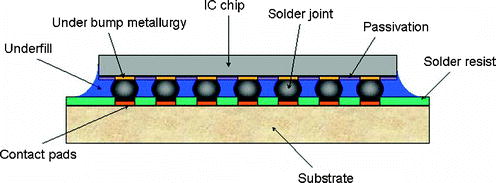
 The last post introduced flip chip ball grid array packages (FCBGA). The key element from a polymer perspective is the use of an underfill to stabilize the solder balls or copper pillars used to electrically connect the IC chip to the substrate as seen in the schematic on the left. Several processes have been developed to place the underfill under the flip chip. The flow chart in Figure 1 shows the various ways underfill can be applied in the flip chip process.
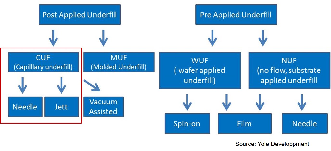
Figure 1. Flip Chip underfill processes and methods (Source: Yole Developpment)
This post will focus on the post-applied underfill methods and specifically capillary underfill methods (red box in Figure 1). In the case of post applied underfill, the IC chip is bumped (or plated with copper pillars) and then attached to the flip chip substrate using a solder reflow process. The temperature of the reflow is governed by the metallurgy of the solder bump or solder paste on the copper pillars. Many of the new reflow process utilize lead free solders and have a 260°C maximum reflow temperature.
After the solder reflow there is a flux cleaning process (or some of the new reflow fluxes are so-called “no-clean flux” eliminating the flux cleaning process. In any case, the underfill is placed under the flip chip using a process called capillary underfill. In the capillary underfill process, the underfill material is typically needle dispensed along the edge of the flip chip die and is pulled under the flip chip by capillary forces. A schematic of the capillary underfill process is shown in Figure 2.
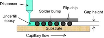
Figure 2. Schematic of the flip chip underfill dispensing process (reference [1])
Typical capillary underfills are supplied in pre-mixed and frozen syringes. After carefully thawing, the underfill syringe is placed on the dispensing equipment. The typical method for underfill dispensing was needle dispensing using a time-pressure dispenser. Most of the newer capillary underfill process use jet dispensing (subject of a future post). For discussion in this post, we will use needle dispensing to point out the key features of the capillary underfill process.
The underfill is typically dispensed as a thin line along either one or two sides of the flip chip. In most cases, multiple passes are required to apply an adequate amount of underfill to completely flow, fill under the chip and form a proper fillet around the edges of the flip chip. Figure 3 shows the flow pattern for a capillary underfill that was dispensed along two sides. Note the flow pattern will aid in minimizing void entrapment during the underfill process.
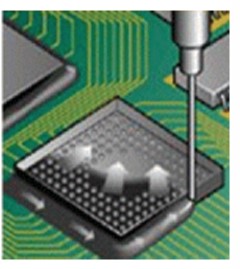
Figure 3. Two sided dispensing pattern for capillary underfill (reference [1])
For the underfill process shown in Figure 2, what are the critical process variables? To get a qualitative feel for the geometry effects, the Hele-Shaw [2] approximation provides an approximation of the filling time and is given in the following equation:

Where:
L= chip length
θ = contact angle
h= gap height
η = viscosity
σ = surface tension
From this relationship, the filling time increases (not what we want) when:
- the chip length (L) and viscosity (η) increase
- the gap height (h) and the surface tension (σ) decrease
Note; the Hele-Shaw approximation does not account for the solder interconnect bump pitch and bump count, but provides a qualitative relationship to understand the geometric parameters during capillary underfill. The packaging trend is to smaller gap heights (lower h) with tighter bump pitch and the die size is getting larger (L) and both of these geometric parameters increase the filling time, thus reduce throughput during manufacturing. A means to compensate for these geometric constraints is to reduce the viscosity. The polymer design challenge is that capillary underfill must have a low coefficient of thermal expansion (CTE) which required high filler loading, which in turn increases the viscosity. From practical standpoint, as the die size increases, the designer should keep the gap height as large as possible.
Another way to reduce the viscosity is to dispense the capillary underfill at elevated temperatures. This is done by heating the manifold and needle (not the syringe) during the dispensing process.
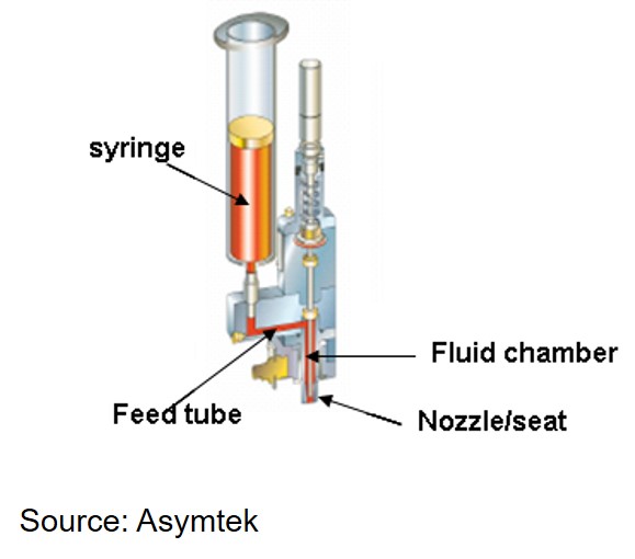
Figure 4. Schematic of a heated jet dispensing nozzle (Source: Asymtek)
In Figure 4, the feed tube, fluid chamber and nozzle are heated in the range of 90-100°C during underfill dispensing. The chemistry of the underfill is tailored to have low reactivity at the dispensing temperatures and fully cure at temperatures in the range of 150-165°C in an oven thermal curing process after the underfill is dispensed. In most processes, the flip chip BGA substrate is also heated to facilitate good flow under the flip chip.
For more information on the polymer properties of capillary underfills see our previous two posts at reference [3] and reference [4].
References:
- B Kim and J. Sung, Capillary-driven Micro Flows for the Underfill Process in Microelectronics Packaging, J. of Mechanical Science and Tech., 26 (12) 2012, p 3751-3759
- J.W. Wan, W. J. Zhang, and D. J. Bergstrom, Recent Advances in Modeling the Underfill Process in Flip-Chip Packaging, Microelectronics Journal, Vol 38, issue 1, January 20017, p. 67-75
Leave a Reply