Guest Post by Dr. Lawrence Judovits, Arkema, and Dr. R. Bruce Prime
We welcome back Dr. R. Bruce Prime along with fellow thermal analyst Dr. Larry Judovits from Arkema for a series of posts on MTDSC.
Modulated temperature differential scanning calorimetry (MTDSC) is a family of techniques where a temperature modulation is overlaid on a linear heating or cooling ramp resulting in a modulated heat flow. Good references include Riga and Judovits, eds., Material Characterization by Dynamic and Modulated Thermal Analytical Techniques, ASTM STP 1402 (2001); Menczel, et al., “Differential Scanning Calorimetry” in Thermal Analysis of Polymers, Menczel and Prime, eds, Wiley, (2009); and Reading and Hourston, eds., Modulated-Temperature Differential Scanning Calorimetry, Springer (2006).
MTDSC allows the separation of overlapping thermal events. Most thermal analysis companies have this technique available. The original and best known of the MTDSC techniques is MDSC by TA Instruments and we will use this as an example of the methodology. In general, use of MTDSC allows the separation of reversing and nonreversing effects from the total heat flow. The total heat flow is the sum of all the thermal events and similar to the heat flow seen in conventional DSC. The reversing heat flow encompasses thermal events that respond to changes in the ramp rate. Events that are reversing are heat capacity and the glass transition. Conversely, those events that do not follow the modulation in the ramp rate will go into the nonreversing heat flow. For thermosets these are the cure exotherm and the enthalpy relaxation endotherm.
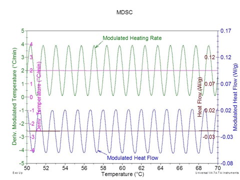
For MDSC, the principal signals are determined from the modulated signals. The total heat flow is calculated as the average value of the modulated heat flow signal. This is done by using a Fourier transform analysis although it could be approximated by taking points halfway between the modulation peaks and can be noted in the figure below.
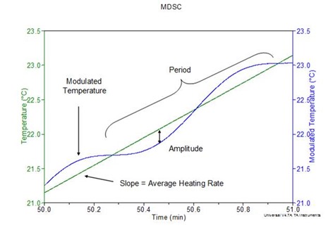
MDSC involves more run parameters than conventional DSC. These parameters are the amplitude, the period, and the ramp rate (also referred to as the heating or cooling rate). The amplitude is the peak height of the modulated temperature in ˚C while the period is the time in seconds needed to complete one modulation cycle as noted in the figure below.
To calculate the reversing heat flow (RHF), first the reversing heat capacity (Cpr) is determined as follows:
where K is the cell constant. Once this calculation has been performed, the RHF can be obtained by simply multiplying the reversing heat capacity signal by the underlying ramp rate (URR) to convert to heat flow in units of power such as mW (1 Watt = 1 J/s). A change in sign is also needed since TA Instruments records its heat flow in the downward or negative direction. Thus
The nonreversing heat flow (NHF) is calculated from the difference between the total heat flow (THF) and the reversing heat flow:
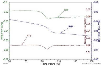
An example of all three principal signals can be seen in the figure below. As can be seen the reversing glass transition is nicely separated from the nonreversing enthalpy relaxation.
 The three principal MDSC signals for a molded polystyrene coffee cup lid. The sample was first heated to above its glass transition, then cooled at 10ºC/min through Tg, and finally reheated at 2 ºC/min using a period of 40 sec and an amplitude of ± 0.212 ºC.
In choosing the conditions for an MDSC run, seven ramp rate options are possible: three heating choices, three cooling choices, and modulation around a single temperature referred to as the quasi-isothermal or QiDSC mode. Since the cooling choices are just the converse to the heating selections, we will limit the discussion to heating. The first is the heat only mode that is commonly used for initial scans. The second possibility is to heat with some cooling where a cooling portion in the ramp occurs due to a sufficiently large amplitude (although the overall average rate is heating). The final heat selection is a modulation that has a zero heating at its slowest rate and can therefore result in a curve with more definition than the heat only mode. This is the mode used in the examples here. A further complication to the selection of the proper parameters is that a poor modulation may occur if the rate is too fast, the amplitude too high, or the period too long. The general rule of thumb is to have at least 4 to 5 cycles through a transition but even more is better. This limits the rate of MDSC and the fastest rate suggested is 5 ˚C/min.
Applications of MTDSC to thermosets can be divided into two categories: heating mode and quasi-isothermal or QiDSC mode. At slow heating rates, generally lower than 2 °C/min, the reaction rate is competitive with the heating rate and as a result vitrification may be observed on heating. Even though vitrification may occur in a standard DSC run it is not observed in the trace. For partially cured thermosets such as prepregs, the glass transition can be separated from the total heat flow when enthalpy relaxation and/or residual cure interfere with measurement of Tg. In standard isothermal DSC the signal is dominated by the cure exotherm, while QiDSC allows measurement of changes in Cp and vitrification in addition to the cure.
Since the amplitude of the temperature modulation will affect the cure kinetics, very high amplitudes should be avoided. Typical modulation amplitudes fitting these criteria are ±1 °C or less. A period of 60 sec is usually a good starting point for most cure experiments although a smaller period allows more modulation through a transition. As discussed previously we recommend slow rates of less than 5 °C/min.
In our next post we describe the application of MTDSC in the heating mode to thermoset cure.


Leave a Reply