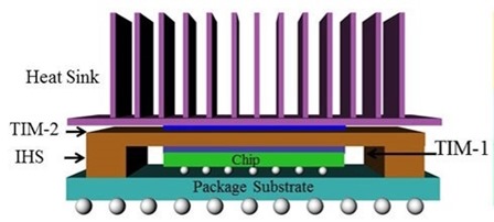
 In many electronic applications, managing the heat dissipation is a challenge. There are two important engineering functions of thermally conductive adhesives; heat spreading to avoid hot spots and heat transfer through a thermal interface material. In the image on the left, there are two thermal interface materials (TIM) being used. One is in contact with the semiconductor chip and facilitates heat removal from the chip into the integrated heat spreader (IHS). This is called TIM-1. A second application of a thermal interface material is called TIM-2, where the TIM is between the heat spreader and the heat sink. There are four types of thermal interface material forms:
- Thermal greases
- Gap filler pads
- Films and tapes
- Phase change materials.
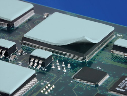
An example of a thermal grease is shown on the top in the following figure (source: Keratherm Thermal Grease KP 12):

The image on the bottom shows gap filler pads on the top of packaged semiconductor chips prior to heat spreader application (photo courtesy of Bergquist Corp). In both of these cases, the use of a TIM will help with heat transfer out of the semiconductor package.
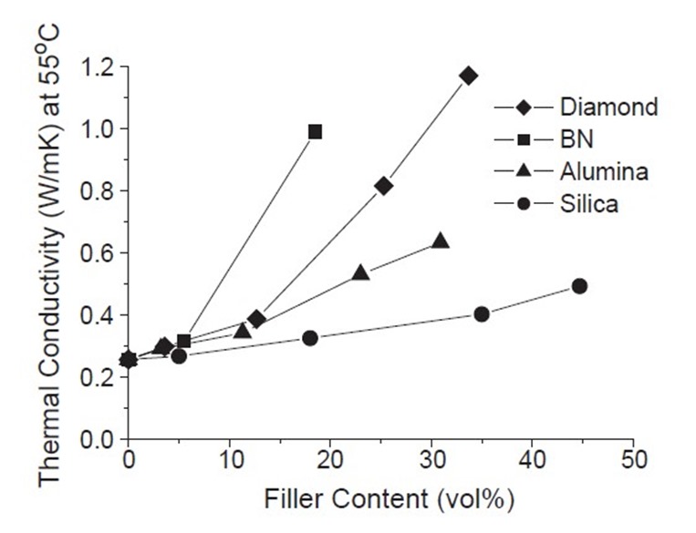
In all of the above the thermal conductivity is achieved using filler technology. The thermal conductivity (k) of an unfilled epoxy is about 0.2 W/m•K. Most unfilled polymers are electrically insulating and require the addition of electrically insulating, thermally conductive fillers. Increasing the thermal conductivity of thermosets that are electrically insulating is a tough technical challenge. The thermal conductivity of a thermoset can be increased to 1 -2.5 W/m•K while maintaining its electrical insulation by the incorporation of fillers like quartz (k = 12 W/m•K), alumina (k = ~30 W/m•K), boron nitride (BN, k = 300 W/m•K) or diamond (k = 2000 W/m•K). Adding thermally conductive fillers can increase the composite thermal conductivity as seen in the following figure:
Figure 1. Thermal conductivity as a function of filler volume percent
In the above plot (from reference 1), the thermal conductivity (TC) is plotted as a function of volume fraction for four types of fillers (diamond, boron nitride (BN), alumina, and silica). One readily observes that silica fillers are not very effective at increasing thermal conductivity. Silica is a very common filler to reduce the coefficient of thermal expansion (we will discuss in a future post). Alumina provides a moderate increase in TC.
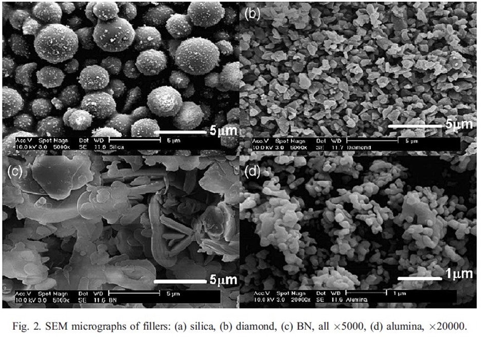
Let’s look a little deeper at why there are significant differences in the effectiveness of different fillers in increase TC. It turns out the filler aspect ratio or geometry plays an important role in the development of thermal conductivity. In figure 1 above, boron nitride (BN) was the most effective filler for increasing thermal conductivity. The morphology of BN is plate like (reference 2). In the work of Lee and Yu (reference 1) they used Scanning Electron Microscopy (SEM) to investigate the filler morphology used in a thermoset matrix. In figure 2, the filler geometries clearly show the spherical nature of the silica and alumina fillers compared with the plate like morphology of the BN fillers.
Due to the effectiveness of the BN filler interactions, at 15 volume percent loading, the thermal conductivity increased nearly 5 fold. In Fig. 1, at 15 volume % loading, the BN filled composite has nearly a 2X larger thermal conductivity compared with the diamond filled composite even though its thermal conductivity is nearly an order of magnitude larger boron nitride. In the first post in this series we gave the example of poker chips versus marbles. Plate-like fillers (i.e. poker chips) will have much larger particle-particle interactions and be more efficient at increasing thermal conductivity. The data in Figures 1 and 2 clearly demonstrates the role of the filler aspect ratio on the thermal conductivity of the filled composite.
In the next post we will investigate how fillers can be used to lower the coefficient of thermal expansion.
References:
- W. Sun Lee and J. Yu, Diamond and Related Materials 14, 1647 (2005).
- K. Sato, H Horibe, T. Shirai, Y. Hotta, H. Nakano, H. Nagai, K Nitsuishi, and K. Watan, J. Mater. Chem. 20, 2749 (2010).


great information !! can you tell what is solution of overheating of cpu ?