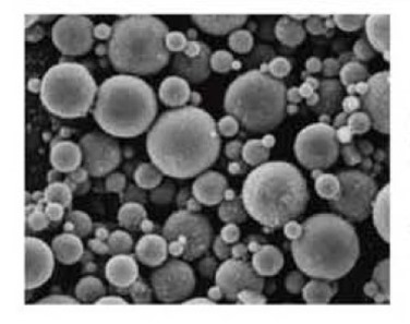
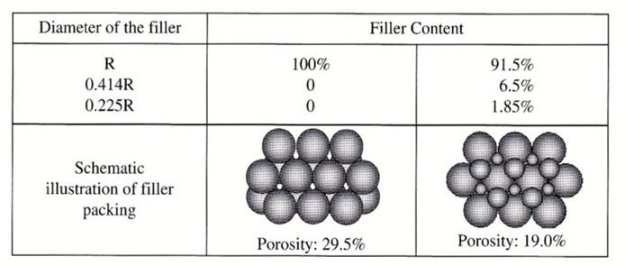
 In the last post we introduced the concept of using a multi-modal particle size distribution to achieve very high packing densities (filler loadings) in thermoset compounds. Remember that applications such as mold compounds, capillary underfills, and some types of encapsulants need to have a low coefficient of thermal expansion (CTE). Epoxy resins (and other thermosets) typically have high CTE’s in the unfilled state. Many types of fillers are used to lower the CTE. Mold compounds, as described in the last post have very high filler loadings. So we want to use multiple particle sizes (as shown in the image on the left) but how do you determine the particle sizes to achieve high filler loading? The image on the left shows a tri-modal particle size distribution. In the following example, we will show you how to calculate what size fillers to use for this type of packing. In Table 1, shows examples of two types of particle size distributions; a mono-disperse filler loading and a tri-modal particle filler loading. The table gives the exact size requirement for a tri-modal particle size distribution.
Table 1. Table of the filler diameter for two cases; mono-disperse filler distribution and tri-modal filler distribution
In the first case, the filler content consists of entirely all particles of radius R. The image shows a schematic illustration of the filler packing. In this case, the porosity is 29.5% (filler fraction of 70.5%). As mentioned before, since commercially available fillers have a wider particle size distribution, this represents an upper limit. In the example using the tri-modal particle sizes, the majority of the particles have a radius of R (in this example, 91.5%). The particle size of the next generation is 0.414R or about 41% of the size of the largest particle. In this example, the medium particle size is 6.5% of the total filler content. The smallest particle size is 0.225R and comprises about 1.85% of the total filler content. For the tri-modal particle size distribution, the porosity is decreased to 19% (filler fraction of 81%). When formulating highly filled thermosets, a close working relationship with your filler supplier is required. It is not only important to know the average particle size, but the particle size distribution. Some commercially available fillers can have quite broad particle size distributions that will significantly influence the particle packing. The largest fillers are typically determined by the mechanical property requirements along with the flow and rheological properties. Once the largest particle size is determined, Table 1 gives the target sizes for the next two generations.
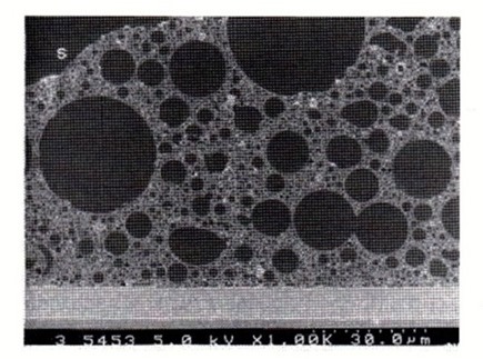
The SEM image in Figure 1 (courtesy Sumitomo) shows a cross-section of an EMC where at least three filler sizes (and possible four) are clearly visible. Note that the particle sizes have a fairly wide distribution for each of the generations of fillers.
Figure 1. SEM image of a mold compound cross-section depicting a multi-modal particle size filler distribution.
In the SEM image in Figure 1, the resin (lighter color) is clearly shown between the fillers. Since the largest particle size is not mono-disperse, the exact calculation of the relationships shown in Table 1 somewhat difficult. I made a quick estimate of the particle size of the second smaller particle and it ranged from 0.32R to 0.45R in fairly close agreement with the relationship given in Table 1.
In or next post we will discuss fillers used to make electrically conductive thermoset adhesives and coatings.


Where is Figure 2 ??? That’s what I need to see in order to determine the other target sizes.
Thank you for catching my typo and carefully reading my blog. There is no Figure 2. You should refer to Table 1 to calculate the radius of the second and third generations.
Thanks for the catch. I corrected the equation. Nice to see our readers are reading our posts carefully.
I had three questions:
1) Could you provide more detail on how is the largest particle size determined for like a conductive adhesive
2) How could one calculate excepted porosity of flake shape fillers and the PSD needed to achieve a target loading percentage?
3) How does one calculate the loading factor needed to achieve CTE target or electrical conductivity target?