![]() In the last two posts we saw how important fillers can be in improving the properties of thermosets. We have covered using thermally conductive fillers to enhance the thermal conductivity of thermoset formulations. Additionally, we saw how the coefficient of thermal expansion (CTE) could be significantly lowered with judicious use of fillers. In many cases it is advantageous to have very high filler loadings to achieve the desired mechanical or physical properties. A good example is a mold compound used to encapsulate a semiconductor chip. In the figure on the left, the black material is an epoxy mold compound (EMC). The schematic cutaway is a quad flat pack with no leads (QFN). The semiconductor chip (blue) is mounted on a leadframe (copper pad under the chip) using a die attach adhesive and the chip is wire bonded to the lead fingers. After the wires are attached, the leadframe is over molded using a EMC. If you look in your computer or see a populated mother board (circuit board with components soldered on the surface), the black packages you see are not the chips, but molded packages. The mold compound is formulated to protect the semiconductor chip and typically has very high filler loading to achieve the desired properties. Typical EMC’s have high filler loadings in the range of 75-90%. So the question is; how do you get high filler loadings in epoxy mold compounds?
In the last two posts we saw how important fillers can be in improving the properties of thermosets. We have covered using thermally conductive fillers to enhance the thermal conductivity of thermoset formulations. Additionally, we saw how the coefficient of thermal expansion (CTE) could be significantly lowered with judicious use of fillers. In many cases it is advantageous to have very high filler loadings to achieve the desired mechanical or physical properties. A good example is a mold compound used to encapsulate a semiconductor chip. In the figure on the left, the black material is an epoxy mold compound (EMC). The schematic cutaway is a quad flat pack with no leads (QFN). The semiconductor chip (blue) is mounted on a leadframe (copper pad under the chip) using a die attach adhesive and the chip is wire bonded to the lead fingers. After the wires are attached, the leadframe is over molded using a EMC. If you look in your computer or see a populated mother board (circuit board with components soldered on the surface), the black packages you see are not the chips, but molded packages. The mold compound is formulated to protect the semiconductor chip and typically has very high filler loading to achieve the desired properties. Typical EMC’s have high filler loadings in the range of 75-90%. So the question is; how do you get high filler loadings in epoxy mold compounds?
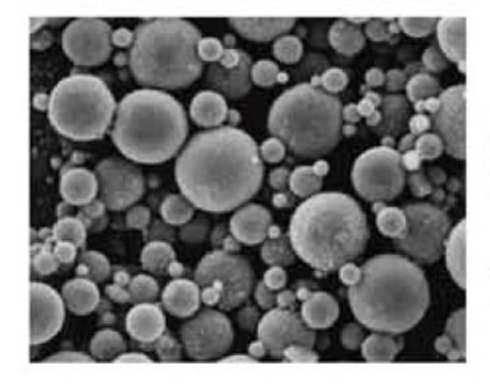
If you take a look at close packing literature, the maximum packing density for single sized spheres is 74% in a face centered cubic configuration. In practice this is never achieved since most of the fillers either don’t have a monodisperse particle size distribution or are not perfect spheres. We saw in the last couple posts that plate-like fillers are very effective at reducing the CTE and increasing thermal conductivity. Since mold compounds must have low viscosity during processing to quickly fill the mold cavity and flow around the wire bonds without damaging them, spherical fillers are used. In typical commercial formulations such as mold compounds, a multimodal particle size distribution is utilized. Figure 1 shows an SEM image of spherical fillers used in a mold compound (courtesy of Sumitomo).
Figure 1: SEM image of filler used in a typical epoxy mold compound
There are clearly three distinct particle sizes used in this example. There are large particles, medium sized particles and then very small particles. This is an example of “generational packing” where the medium sized particles fit in the interstices formed by the largest particles. In turn, the smallest particles can fit into the interstices formed by the medium sized particles (as well as the interstices of the largest particles). In this manner, very high filler loadings can be achieved on the order of 90%.
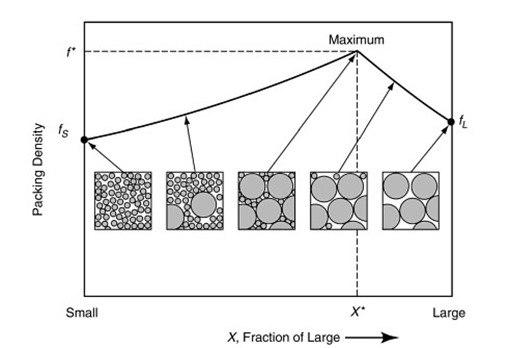
Let’s take a look at why you can achieve high packing density with multiple sized fillers. In Figure 2, a schematic is shown that depicts the packing density as a function of filler size (ref. 1).
This image tells an interesting story about how the packing density changes as a function of filler size and loading for a bimodal particle size distribution. On the left is the packing density for small monodisperse fillers. On the far right is the packing density for monodisperse large particles. As mentioned above the maximum packing density for a face centered cubic packing geometry is 74%. The interesting feature is that as larger particles are added (replacing some of the smaller particles), the packing density steadily increases. The maximum packing density occurs when the small fillers nearly completely fill the interstices between the larger fillers. Again, since commercial fillers are not typically monodisperse, it is difficult to exactly predict the volume fraction of the large filler at the maximum. As the amount of large particles continues to increase (with the elimination of some of the smaller particles), the packing density begins to decrease.
This schematic clearly depicts why commercial mold compounds have a multimodal particle size distribution that enables high packing density. In the next post we will describe how to calculate the optimum particle sizes to get high packing densities.
Reference;
- Handbook of Mathematical Relations in Particulate Materials Processing, RM German and SJ Park, John Wiley & Sons, 2008


High fluidity is a desirable characteristic of brazing filler metal because capillary attraction may be insufficient to cause a viscous filler metal to run into tight fitting joints.