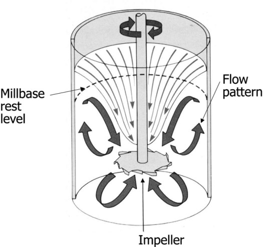
The last post described using a single shaft mixer with a cowles blade (as shown above). The single shaft method is good for simple dispersions where in-situ vacuum degassing is not critical. However, if vacuum degassing is required, multi shaft mixers provide an efficient means to disperse fillers under vacuum.
Dual-shaft mixers are used to produce a wide range of viscous formulations. Several manufacturers market dual-shaft mixers (Ross, Meyers, Hockmeyer, Mixer Direct, and others). The vast majority of dual-shaft mixers also have vacuum capability allowing both dispersion and vacuum degassing during filler incorporation. A dual-shaft mixer has a high speed cowles dispersion blade on one shaft and the second shaft drives a low speed helical or sweep blade used to sweep material off the vessel wall and into the dispersion blade.
The tip speed of the cowles blade is in the range of 500 – 5,000 ft/min (see the previous post for details of calculating the tip speed) and is typically used to break agglomerates and “wet-out” the filler particles. A disperser blade on a single shaft mixer produces acceptable flow patterns in fluids up to approximately 50,000 cP. If the viscosity of the desired final mixture is higher than this, the formulation will not adequately flow into the dispersion blade and will stagnate around the walls of the vessel (see schematic figure above). Additionally, there will potentially be over-mixing in the vicinity of the cowles blade due to inadequate material flow into the blade.
In order to overcome the flow limitation and expand the viscosity range to several hundred thousand centipoises, a second shaft with an anchor or sweep blade is used. The low speed sweep blade is used to “sweep” the material from the vessel walls and bottom into the dispersion blade. A dual-shaft mixer may be used to mix highly-filled formulations up to approximately 1 million cP [1].
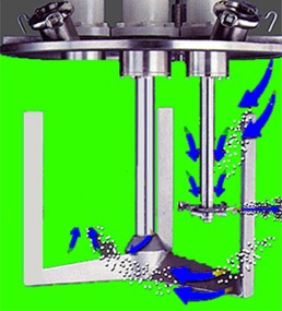
A typical dual-shaft mixer is shown in Figure 1.
Figure 1. Dual-shaft mixer with dispersion blade and sweep blade.
Since the dispersing blade shaft is stationary, as the viscosity increases during mixing, material flow to the dispersing blade would become limited. To overcome this issue, a slowly rotating “sweep” blade is used to move material from the vessel wall into the cowles blade. This is seen in Figure 1 with the blue arrows. Many of the sweep blades are also fitted with Teflon scrapers on both the sides and bottom to help with pulling material from the walls and bottom. Additionally, two dispersion blades can be placed on the high-speed shaft. One cowles blade would be mounted at the lowest point on the high-speed shaft and the second cowles blade may be located at a location above the lower cowles blade, but typically 1 blade diameter below the fluid surface. The second upper cowles blade helps to form a strong vortex to rapidly draw more filler materials into the dispersion zone. The upper blade can be either the same size or slightly smaller than the lower dispersing blade. For larger vessels in manufacturing, dual dispersing blades will improve the dispersion quality and shorten the mixing time.
When adding large amounts of fillers, air is introduced when the filler powders are added to the resin formulation. Vacuum degassing is very beneficial in preventing air entrapment, or typically used to remove air entrained during the filler addition. In Figure 1, the top plate will seat securely on the top rim of the mixing vessel (not shown in Figure 1) allowing for a vacuum to be applied. If the dispersing blade is too fast, additional air will be pulled into the disperser. In many applications, the liquid components are mixed first (resins and liquid additives) and then the fillers are added to the liquid. Filler addition can be manual, whereby the proper weight of fillers is simply placed on top of the liquid, the mixing vessel closed, and vacuum applied prior to starting the mixing blades. The vacuum degas step prior to incorporating the fillers into the liquid aids in removing air between the filler particles and facilitates the overall mixing and wetting. It is good practice to vacuum degas for at least 15 minutes or so at a vacuum of at least 29 mm Hg. Selection of the right vacuum pump is critical. Care also must be taken to ensure the rim of the mixing vessel and the O-ring on the top plate are clean and free of resin and filler particles.
At the beginning of the filler degassing process, carefully observe the powders to make sure the fillers don’t “fly” and get sucked into the vacuum pump. A practical tip would be to install a manual vacuum “break” valve in the top plate, or in-line with the vacuum pump to allow manual vacuum regulation during the initial vacuum filler degas process. When the vacuum is pulled on both the fillers and the liquid resins, air released from the liquid may cause small “volcanoes” to form in the liquid resin and potentially cause the fillers to fly. It would be a bad day for the process engineer if a large amount of fillers got sucked into the vacuum pump! (Hopefully you have a trap between the mixing vessel and the vacuum pump).
Once the vacuum degas step is completed, the sweep blade and dispersion blade are started. An additional benefit of the sweep blade is to aid in releasing the air pockets formed during filler addition. When the mixing process starts, the operator must carefully observe the fluid level in the mixer. The powerful vacuum will cause the highly-filled formulation to “foam” and expand dramatically. Here again, having the manual vacuum “break” valve in the top plate, or in-line with the vacuum pump allows manual vacuum regulation during the initial vacuum degas process. During the vacuum mixing step, a vacuum level of at least 29 mm Hg is desired in order to achieve efficient vacuum degassing.
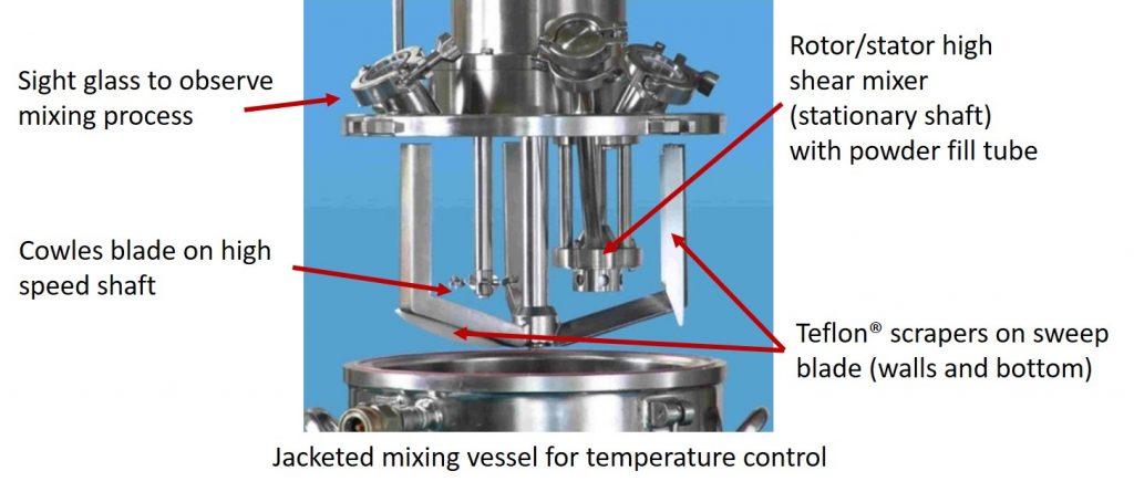
Figure 2. Triple-shaft mixer (Courtesy of Charles Ross & Son Company)
Figure 2 shows some of the key features of a vacuum triple-shaft mixer. In this case, the third shaft is stationary and is outfitted with a high shear rotor/stator mixer. Another configuration would be to use two high-speed shafts with dispersion blades. In either case, the sweep blade is shown with Teflon® scrapers on both the sides and bottom. The bottom of the sweep blade is not flat since the mixing vessel in this photo has a sloped bottom. The sweep blades can be used on either sloped or flat bottom mixing vessels. In Figure 2, a single cowles blade is shown installed at the bottom of the high-speed shaft. A subsequent post will describe the use and operation of the rotor/stator high speed disperser.
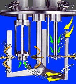
Figure 3. Triple-shaft mixer showing flow patterns (Courtesy of Charles Ross & Son Company)
In Figure 3, a schematic of the flow patterns is shown for the triple-shaft mixer configuration in Figure 2. The material flow into the cowles blade is through the vortex caused by the high blade speed. In the case of the rotor/stator, the material flow is into the rotor/stator on the bottom side of the high-speed stationary disperser. In both cases, the material flow into the dispersing zones is highly facilitated by the sweep blades. Additionally, the sweep blades aids in the vacuum degassing process.
References
- Charles Ross & Son Company, Technical Bulleting MTI 92, Basics of Dual Shaft Mixers. See https://www.mixers.com/resources/mixing-technology-reports/


Leave a Reply