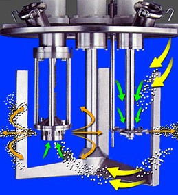
The last post discussed multi-shaft mixers where the two or three mixing shafts were stationary, and the sweep blade was used to move material off of the sidewalls and into the mixing zone. In the double planetary mixer, the mixing blades rotate on their own shaft (axis) while the shafts rotate around in the mixing vessel on a common axis. The as the blades orbit the mixing vessel, they advance along the inside wall and move material into the interior. Additional shearing occurs as the blades pass one another.
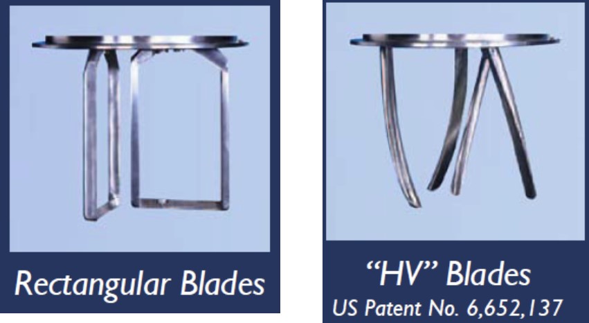
Figure 1 shows two types of blades used in double planetary mixers.
Figure 1. Rectangular and helical blades (Courtesy of Ross & Son Company)
For dispersions with viscosities up to 1.5 million centipoise double planetary mixers with standard rectangular blades work well. The HV blades extend the range of viscosities up to approximately 6 million centipoise. When using rectangular blades, high shear dispersive mixing is more efficient at higher viscosities. Double planetary mixers operate at low speeds and higher product viscosities yield better agglomerate dispersion. The ideal viscosity range for rectangular blades is in the range of 100,000 cP to about 2 million cP [1]. In many manufacturing operations the fillers are pre-wet in one (or more) low viscosity liquids resulting in a higher viscosity mixture, and then the final mix is made in the double planetary mixer.
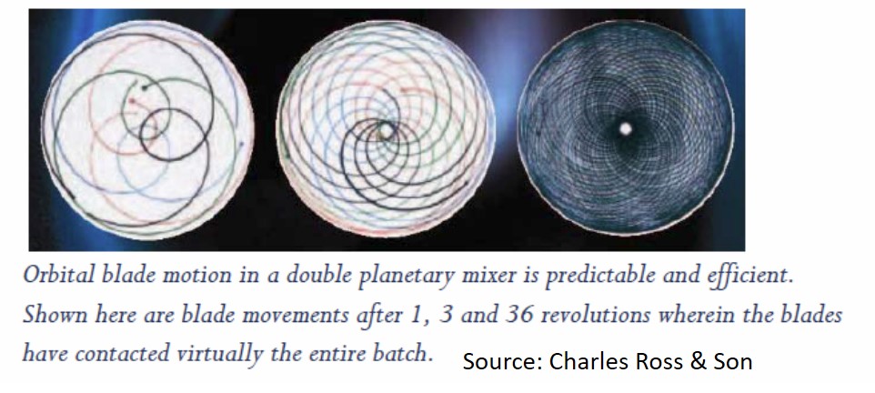
Figure 2 shows the trajectory of a rectangular blade in the mixing vessel.
Figure 2. Double planetary mixer blade motion (Source: Charles Ross & Son Company)
The blades generate shearing forces as the leading edge of the blade sweeps along the vessel wall and the blade pass each other during rotation. The material is moved towards the center of the mixing vessel. The HV blades are very useful for very high viscosity dispersions in that the blade design facilitates the material movement down into the mixture preventing the highly-filled compound from climbing up the blades.
There are several manufacturers of double planetary mixers with various mixing vessel sizes, vacuum capability, and automation. For example, Charles Ross & Son Company has double planetary mixers with mixing vessels from ½ pint to more than 750 gallons. Small double planetary mixers are quite useful in the lab environment during formulation development and filler screening.
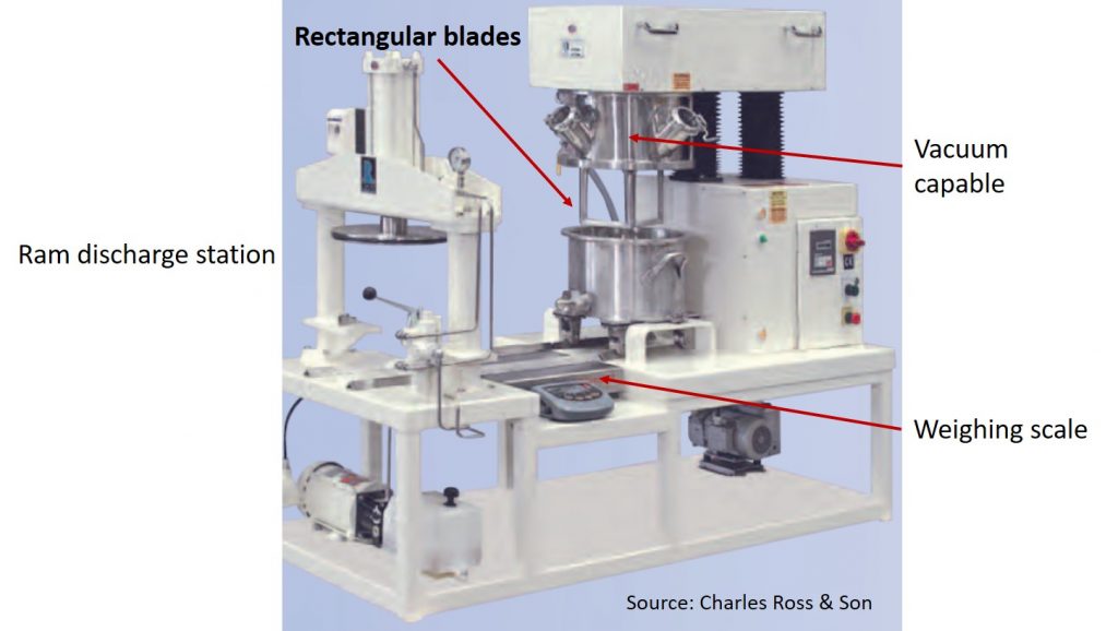
Figure 3. Double planetary mixer with weigh station and ram discharge (Source: Ross & Son Company)
Figure 3 shows a very nice small batch or pilot scale double planetary mixing operation utilizing two rectangular blades. The weigh scale in the center of the track is a nice feature allowing the mixing vessel to be tared prior to material addition and then subsequent materials may be charged into the mixing vessel and precisely weighed. This also provides operator safety since during each charge, the mixing vessel doesn’t need to be manually removed and placed on a weighing scale close by. In many cases, the order of addition requires multiple steps such as adding multiple liquid components, mixing, then adding fillers. With each material addition, the mixing vessel is typically tared (weight set to zero) and additional material is added to the desired weight. Having the weigh scale close to the mixing operation facilitates precise weighing of each component.
Let’s take a minute to discuss order of addition. In many highly-filled systems, the order of material addition is important. During development and scale-up, it is critical to conduct experiments to establish the proper order of addition to achieve the desired final properties. Don’t cut corners and skip this step. Additionally, during the order of addition experiments, this is a good time to investigate mixing speed, mixing time, vacuum hold times, etc. For most systems the following is a good guideline:
- Mix liquids first such as low viscosity resins, reactive diluents, liquid additives
- Dissolve soluble ingredients if necessary
- Add fillers, tougheners, solid viscosity modifiers like fumed silica and disperse using high shear mixing
- Vacuum degas during and after filler addition to remove trapped air if necessary
- Add curing agents and catalysts last
Once the mixing is completed, the mixing vessel is moved to the ram discharge station at the left side in Figure 3. Typical final viscosities are fairly high after proper filler addition and dispersion and gravity discharging is not an option. Also, hand scooping and scraping is time consuming and may lead to contamination. The most practical approach is to use a ram discharge method. The mix vessel is placed in the discharge station (at the left in Figure 3) and the platen is lowered into the vessel. An O-ring around the periphery of the discharge platen makes a snug fit with the vessel wall providing a “wiping” action as the ram pushes the platen into the mixing vessel. As the ram moves down into the mixing vessel, the finished product exits via a valve in the bottom or side of the vessel. A subsequent post will provide more details on the ram discharge process.
The next post will cover hybrid mixers that combine some of the mixing geometries recently discussed into new types of highly efficient mixers.
References:
- Charles Ross & Son Company, Mixing Technology Insight #105


Leave a Reply