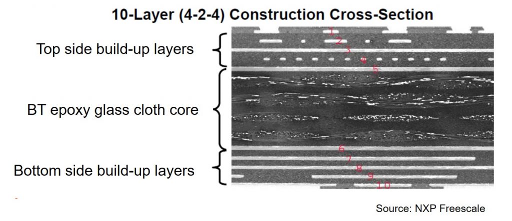
Figure 1. An example of a HDI substrate used for a Flip Chip BGA (source: NXP Freescale)
The last post described High Density Interconnect (HDI) substrates. This post will discuss the build-up layer technologies used to make the sequential circuit layers on each side of the BT epoxy core. In Figure 1, a cross-section of a 4+2+4 HDI substrate is shown. There are 4 build-up layers on each side of the 2 layer core. The circuit layers are noted as 1-10 in red in Figure 1. Notice the core contains a woven glass cloth as seen by the fiber bundles coming out of the plane of the cross-section towards the reader and long fibers running parallel to the plane of the cross-section. The four layers of build-up film on each side of the core do not have glass cloth (for ease of laser drilling microvias). The purpose of the multiple layers of build-up films is to fan-out the small bump pitch from the flip chip to the much larger bump pitch of the solder ball used to connect the substrate to the printed circuit board.
There are two types of build-up technologies utilized:
- Build up films
- Resin coated copper (RCC)
The most popular build-up technology was pioneered by Ajinomoto Fine-Techno Co., Inc. and are called Ajinomoto build-up films (ABF).
Figure 2. ABF cross section (source: Ajinomoto Fine-Techno Co.)
ABF product is made by coating the filled resin in thicknesses of 10-100 µm onto a 38 µm PET carrier support film and protecting the top surface with a 16 µm polypropylene cover sheet as seen in Figure 2. (Note: the exact type of filler is proprietary and has not been disclosed, but it is likely a specialized silica filler to enhance the mechanical properties and not impact the laser drilling and electrical properties). The ABF film is applied to the top and bottom surfaces of the circuitized BT epoxy cores using a vacuum lamination process.
Figure 3. Vacuum lamination process for ABF
Figure 3 shows the high level process flow for the vacuum lamination of ABF to the core. During layup, the polypropylene protective cover layer is removed and the film side is placed in contact with the top and bottom surfaces of the core. The lamination process softens and flows the ABF around the circuit lines and fills in the microvias. After lamination and cooling to room temperature, the PET carrier film is removed and the laminated structure is post cured in a hot air oven at 180-190°C. The fully cured structures are subsequently processed to form the vias, plated and tested. The detailed process flow may be obtained by clicking here.
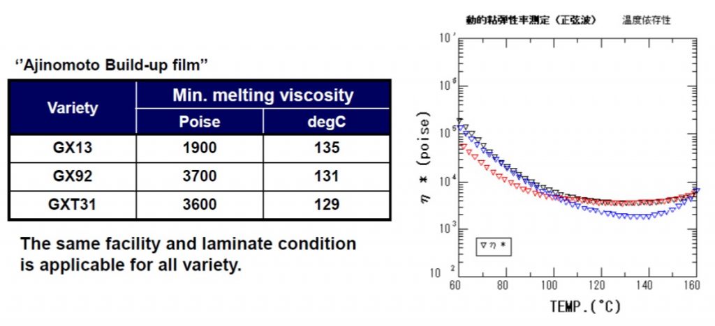
Figure 4. Melt viscosity profiles for the ABF GX13, GX19, and GXT 31 (source: Ajinomoto Fine-Techno Co.)
The viscosity plot in Figure 4 shows the complex viscosity (η*) as a function of temperature for a simulated lamination profile. During lamination, the temperature will increase with a controlled heating rate to the final lamination temperature in the range of 160-180°C. As the temperature increases, the build-up film softens with the viscosity decreasing by about an order of magnitude. The lower viscosity allows the build-up film to flow into microvias and around circuit lines. Additionally, the lower viscosity aids in wetting the BT epoxy core surface allowing for good adhesion of the build-up film to the core. As the build-up film begins to cure (i.e. the molecular weight increases with chemical reaction and crosslinking) the viscosity increases. In the viscosity curves in Figure 4, there is a distinct minimum viscosity and the actual values of ηmin are given in the table. The Ajinomoto description states the lamination process is the same for all of the various products.
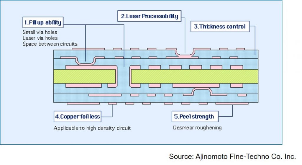
Figure 5. Process advantages of ABF (source: Ajinomoto Fine-Techno Co.)
In Figure 5, a schematic is shown to highlight the advantages of the Ajinomoto build-up film technology. The major advantage of the build-up film approach is the ability to flow to fill small via holes and laser vias as well as covering the space between circuit traces. The small vias are formed using laser drilling and the build-up films are formulated to have excellent compatibility with laser drilling systems. During the coating of the build-up films, the thickness can be tailored to achieve the desired spacing between circuit layers. The coating thickness is precisely controlled during coating to achieve a very uniform build-up film thickness. The build-up films also have high adhesion (peel) strength to the plated copper vias and circuit traces. Additionally, the copper vias and circuit traces are plated and thus don’t require the use of copper foils.
The next post will go into more details into the chemistry of ABF and cover the resin coated copper product and process.


When the ABF is cured does it creep when exposed to temps of 130C ?
What companies make the ABF resin? Thank you