In the last post in this series we introduced the embedded wafer level package concept. In this post we will dive in a little deeper and look at the process and some of the polymer challenges.
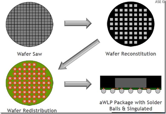
A high level overview may be seen in the next figure (source: ASE Group)
The finished wafer is singlulated using traditional dicing methods to yield individual chips that are mounted on a substrate to form a “reconstituted” wafer. The density of the chips on the reconstituted wafer is governed by the size of the fanout required by the redistribution layer. The chips are mounted face-down on the carrier with care to ensure precise and repeatable placement. The wafer and chip array is over molded using a specially developed mold compound. We will discuss some of the key mold compound material parameters later. In the upper right corner, the reconstituted wafer is seen after molding. Notice that significantly less chips are mounted on the reconstituted wafer. After molding the back side of the reconstituted wafer is polished to ensure a planar surface. An addition thin layer of epoxy mold compound is then applied to the backside to eventually protect the top of the eWLP package. The next major step is to apply a polymer redistribution layer on the top side (exposed bumps from the chips are now accessible). Typically several layers of redistribution layers are applied and photoimaged. In the lower left corner of the figure above, the redistribution layers have been imaged and plated. The next step is to apply the desired interconnection method (either solder bump or plate copper pillar’s) onto each chip. The final step is to singulate the individual packages from the reconstituted wafer.
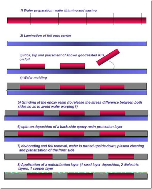
The detailed process flow (Source: Infineon) is given in the following figures:
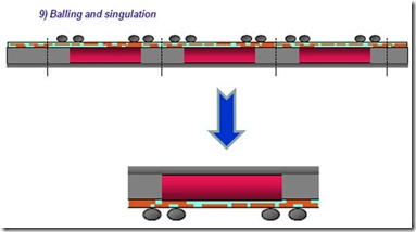
The final interconnect attach (in this case solder ball bumping) and singulation is performed to yield the final package:
Polymer Challenges
Mold Compound optimization is a key enabler for embedded wafer level packaging. The molding process requires a mold compound with low viscosity and a thixotropic (shear thinning) index near 1 which means at the molding temperature the highly filled liquid is Newtonian (no shear rate dependence). In order to control the warpage and die shift, the filler content needed to be increased to 92 to 95% which impacts the viscosity and flow. To achieve these high loading levels, multi-modal silica particle size distributions were used. In addition, the resin-particle interactions play a role in the viscosity so care must be taken to optimize the surface of the fillers. This is critical as the filler size decreases, resulting in a large increase in the surface area and thus more particle-particle interactions. In many cases, the fully cured mold compound needs to be laser drillable to enable package stacking.
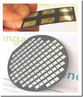
In the picture on the left, the top image shows a portion of the embedded die surrounded by mold compound. The image on the bottom is a reconstituted wafer after molding.
Key material properties are:
- Low CTE to match silicon
- Controlled shrinkage
- Low stress after molding
Source: NXP
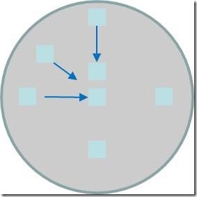
Since the step after molding involves depositing and imaging the redistribution layers, the cure shrinkage needs to be uniform. During curing, the dies will shift toward the center of the wafer, the farther toward the edge the larger the shift. In the figure below, if the shrinkage is not uniform, then the amount of movement will not be consistent across the wafer making registration of the redistribution layer photomask and the imaging process a challenge. Careful formulation of both the resins (optimized for low cure shrinkage) and surface treated fillers for CTE control is necessary for high yield processing.
One can see that polymers play a critical role in the packaging and reliability of 2.5D electronic packages used in many applications such as smartphone, computer, and other complex electronic devices.

Leave a Reply