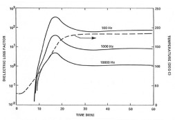
 In this post will build on the basics presented in Parts 1-4. Back at IBM I was developing a fundamental understanding of the composite lamination process used to fabricate very expensive multilayer circuit boards. I was looking for a way to measure the viscosity in-situ during the lamination process but was challenged with how to embed a rheometer in a 10 opening manufacturing press!
After I met Prof. Senturia and Norman Sheppard at a Thermoset Gordon Conference and was introduced to their nifty microdielectrometer (which was commercialized by Micromet Instruments), I went back to my IBM lab and started to tinker around. My goal was to embed the microdielectric sensor in the bottom plate of my rheometer and measure the complex viscosity and dielectric loss factor simultaneously.
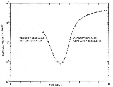
The following figure depicts the viscosity profile for a B-staged epoxy prepreg during lamination.
As the temperature ramps in the press, the viscosity is fairly high since the prepreg is below it’s glass transition temperature. As the prepreg is heated through Tg, the viscosity begins to drop dramatically. This is due to the temperature dependence of the now liquid resin. (Remember from previous posts that typical prepreg for circuit board lamination is an ungelled glass and has a Tg around 50-60oC).
The viscosity continues to decrease until the resin polymerization and crosslinking start. When the crosslinking reaction leads to a higher molecular weight and thus higher viscosity, the viscosity increase due to crosslinking now dominates and the viscosity rapidly increases and eventually reaches a plateau (for small amplitude oscillatory measurements, we can monitor the viscosity through the entire cure).
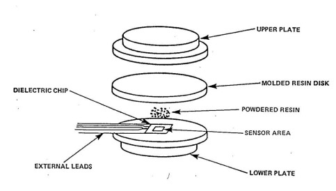
The following figure shows the set-up that was used to measure the dielectric response during a rheometer run.
In this work, a Rheometrics System Four rheometer with disposable plates was used for the rheology measurements. The disposable plates allowed a small slot to be machined in the bottom plate to accommodate the Micromet Instruments dielectric sensor. To ensure good contact with the disposable parallel plates, a process was developed to mold a compacted resin disk using the prepreg powder. The molded disk was free of trapped air and was solid (the molding process was done above Tg, but at a low enough temperature that the cure reaction did not occur). In order to get good contact with the comb electrodes, a small amount of prepreg powder was placed over the comb electrodes prior to inserting the disk between the parallel plates. This ensured good electrode contact allowing a dielectric signal to be obtained as the prepreg went through the Tg.
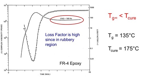
In the following figure, the dielectric loss factor (solid line)and the complex viscosity measured simultaneously are plotted as a function of time. The temperature was ramped in the rheometer at approximately 5oC/minute to a final temperature of 175oC:
As the resin softened at the glass transition temperature, the viscosity decreased rapidly and at the same point, the dielectric loss factor increased rapidly. As the segmental mobility increased after passing through the Tg, the ionic mobility increased and thus the ionic conductivity increased. In these studies, the ionic conductivity provided the dominant signal and thus we will focus on the loss factor. Since the ionic conductivity is inversely related to the viscosity, one observes a maximum in the loss factor close to the minimum in the viscosity. As the resin continues to cure, the complex viscosity achieves a plateau indicating completion of the cure. In this case the fully cured Tg was 135oC and the final cure temperature was 175oC. At 175oC, the fully cured epoxy resin is in the rubbery region. One can readily observe how the dielectric loss signal can be a useful probe of the curing process.
In subsequent posts we will discuss in more detail how the dielectric response changes during curing.


Leave a Reply