Guest Post by Huan Lee, Lambient Technologies
In this last post I want to pass on some tips for successful dielectric cure monitoring. Most seem obvious in retrospect, but I found that the simplicity of the method—place a sample on the sensor, heat and go away for lunch—sometimes caused me to forget how care and good practice go a long way to making good measurements.
Preparing the sensor
Remove oils or other contaminants by cleaning sensors with acetone, alcohol or other solvent
- Remove adsorbed solvents, which might interfere with test measurements in air, by heating sensors above 100 °C for a short time
Prevent material from adhering to reusable sensors by applying silicone or non‑conductive mold release, as shown in Figure 1
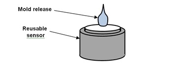 Figure 1. Apply mold release to reusable sensors
Prevent short circuits by avoiding contact between sensor bond pads and electrically conductive surfaces
- Cover bond pads with Kapton® or polyimide tape, as shown in Figure 2
 Figure 2. Insulating the bond pad area
Run sensor leads parallel to each other to reduce capacitance between leads
- Don’t use twisted leads, which increase cable or base capacitance
Laying up the sample
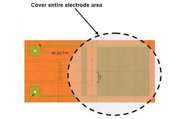
Place sample over entire electrode area, as shown in Figure 3
Figure 3. Sample application area on sensor
Use samples thicker than the separation between interdigitated electrodes
- When the sample is thinner than the electrode separation, the sensor will also detect air or material on the top side of the sample
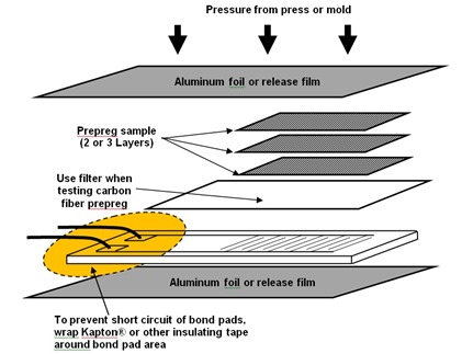
Stack at least two or three layers of prepreg on top of a sensor, to ensure enough resin for good measurements
Use a filter between the sensor and materials containing graphite or conductive fibers, as shown in Figure 4
- Glass cloth with small pore size, fiberglass felt or laboratory filter paper are good filter materials
Use aluminum foil or release film above and below the lay-up, as shown in Figure 4, to prevent the sample from adhering to platen or mold surfaces
Apply pressure to solid samples, or solid samples that melt during processing, for good contact with the sensor
Figure 4. Suggested Lay-up for prepregs
Reducing measurement noise
Don’t use long, unshielded leads, which act like antennas and can pick up interference
- Signal levels at the end of cure are low and measurements are more susceptible to noise at this time
- Use coaxial cable with guarded or grounded shields
Don’t place the sensor on or near large ungrounded metal surfaces
- Ungrounded metal acts like an antenna that can pick up noise, which the sensor detects
- round metal surfaces around the sensor
Don’t place power cords near the sensor
- AC mains voltages are around 100 – 240 VAC but sensor signals may be in the range of only 10 mV
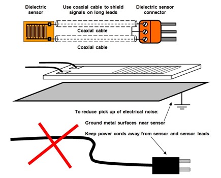 Figure 5. Ways to reduce noise in dielectric sensors
Interpretating dielectric data
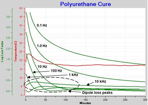
Do look at loss factor, as in Figure 6, when studying the dipole response
- Total loss factor is the sum of loss from the flow of mobile ions and the loss from dipole rotation
- Using loss factor makes it easier to see and separate the mobile ion response from the dipole response
- Loss factor is inversely proportional to frequency when mobile ions dominate response
Figure 6. Loss factor for curing of polyurethane
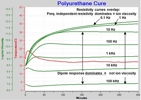
Do look at resistivity from multiple frequencies, as in Figure 7, to determine ion viscosity
- Ion viscosity indicates cure state
- Proportional to change in viscosity before gelation
- Proportional to change in modulus after gelation
- Ion viscosity is frequency independent resistivity due to mobile ions
- Ion viscosity dominates where curves from different frequencies closely or completely overlap
- Dipole response dominates where curves from different frequencies do not overlap
Figure 7. Resistivity of curing polyurethane (plotted against ion viscosity axis)
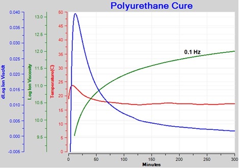
Do use ion viscosity from a single, optimum frequency—if possible—to calculate slope, as shown in Figure 8
- Lower frequencies show ion viscosity response better for whole cure
- Higher frequencies show dipole response better at end of cure
Figure 8. Ion viscosity and slope for curing polyurethane
Conclusion
With proper sample preparation, lay-up, shielding of leads and attention to the electrical environment it is possible to make good, reproducible measurements of dielectric properties for monitoring the cure of thermoset and composite materials.
209 Newbury Street, 3rd Floor
Boston, MA 02116
617-266-2837
email: info@lambient.com


Leave a Reply